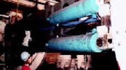
This pair of 14-in. bore hydraulic cylinders, along with a pair on the other side, provides forward thrust and steers the cutter head. Together, these cylinders produce 1.5 million lb of thrust.
Complete tunnel boring machine consists of multiple sections that are assembled on-site.
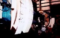
The gripper shoe (foreground), secures boring machine as cutter head (behind people) moves forward. A pair of torque cylinders secures the front section of the machine during cutting.
Most tunneling projects receive little fanfare beyond local coverage. And service tunnels for sewer systems and other utilities usually receive no press coverage at all and are taken for granted by the millions of people reaping the benefits of them every day. Recently, however, educators in northeast Ohio visited Robbins Co., Solon, Ohio, manufacturer's of tunnel boring equipment. The only media coverage was provided by Hydraulics & Pneumatics .
A rare opportunity
The event was coordinated by Greg Gordon, director of Fluid Power Technology at Ohio State University's Agricultural Technical Institute, Wooster, Ohio. Its purpose was to show these educators, first-hand, of the technology behind machines that can bore passageways more than 20-ft in diameter through solid rock. Gordon was able to convince Robbins of the merits of opening its doors to share its expertise with more than a dozen visitors, primarily vocational school and high school science and technology instructors.
The main speaker and tour guide for the event was Gary Thomas, production manager at Robbins, and a former student of Gordon's and graduate of Ohio State's main campus in Columbus. Thomas explained the technology and challenges of boring tunnels through rock, soft earth, and everything in between.
Visitors then divided into small groups and toured the Robbins facility. Visitors entered the manufacturing plant to observe the beginnings of the construction, where steel members are cut, welded and machined into frame assemblies for subsequent fitting with hydraulic, mechanical, pneumatic and electrical components into a finished boring machine. Robbins has the capability and inventory to refurbish used machines to like-new condition, customizing them to the specific application, or creating a new machine from scratch.
On this particular evening, visitors were able to view two machines that were undergoing final assembly. The larger of the two can bore tunnels 22 ft in diameter. It consists of the main machine and seven 40-ft long trailing deck sections that, when assembled, will bring the boring unit's total assembled length to approximately 350 ft and weight to over 450 tons. After final testing, the machine will be disassembled and transported in pieces to the work site, dropped down through a 60-ft diameter vertical shaft into the tunnel, where it will then be reassembled.
Learning first-hand
As each group toured the facility, Thomas and Eric Doan, another guide from Robbins, showed visitors key features of the machines and explained their function in the boring operations. With the 22-ft. machine as an example, Thomas explained that the front section of the machine is "where the action is."
He continued, "Once the machine enters the tunnel opening, a pair of hydraulic cylinders (gripper shoes) are actuated at 4500 psi to produce in excess of 4 million lb of force against the sides of the tunnel wall to keep the machine stationary. A pair of torque cylinders provide stability. Without them, if the cutter head became lodged in the rock face, the 22 million lb-in. drive torque could rotate the entire machine instead of just the cutter head."
With the anchors firmly planted against the tunnel walls, the cutter head is powered by a gear train consisting of seven electric motors and planetary gear drives. Each 450-hp motor is explosion-proof, vibration and corrosion resistant, mine-duty rated, and engaged through a hydraulic clutch. Each motor engages the gearbox through a hydraulic clutch.
An assembly of four hydraulic propel cylinders push the cutter head forward into the rock face with up to 1.5 million lbs. of thrust, with a working stroke of 8 to 10 ft. The machine doesn't actually cut the rock, instead, as the head rotates, numerous wheels roll over the surface of the rock face. Each wheel impacts and fractures the rock into smaller pieces.
Thomas explained, "The cutter head rotates at about 9 rpm, and 60 of these wheels chip away the rock face with each revolution. This generates a huge amount of debris that is carried away by a series of conveyors, all powered by hydraulics."
The four thrust cylinders also provide steering, because tunnels are almost never a straight shot. A series of hydraulically actuated feet control elevation. "For how big this machine is, it's actually pretty maneuverable. "When necessary," added Thomas, "it can turn a 60-ft radius arc. Even under the worst ground conditions, it can bore through the hardest solid rock at a pace of about 1 ft/hr."
Post-boring operations
As the conveyors transport the pulverized rock out of the tunnel fans constantly draw in fresh air and route dust and dirt-laden exhaust through scrubbers before releasing the air into the environment. The scrubbers clean air and a slurry of water, dust, dirt, and chips.
Once a fresh section has been bored, the machine erects reinforcing materials such as temporary steel ring beams, wood timbers, rock bolts, steel net, corrugated steel, etc. Upon completion of the tunnel and removal of the machine, permanent lining consists of reinforced concrete segments.
Thomas said a machine typically requires about 20,000 labor-hours to build, which takes about five to six months. "A machine of this size may run $4 million to $5 million. But there isn't much profit margin. Most of our revenue comes from support service once the machine is in operation."


