Accumulators store pressure in a reservoir in which hydraulic fluid is held under pressure by an external source. That external source can be a compressed gas, a spring, or a weight. They are installed in hydraulic systems for two main purposes: to store energy and to smooth out pulsations.
As energy storage, accumulators typically allow the hydraulic system to use a smaller pump because they amass energy from the pump during periods of low demand. This energy is available for instantaneous use, and is released on demand at a rate many times greater than what could be supplied by the pump alone. As a pulsation or surge damper, accumulators cushion the hydraulic hammer, reducing shocks caused by rapid operation or sudden starting and stopping of cylinders in a hydraulic circuit.
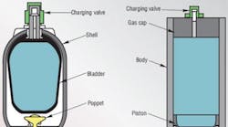
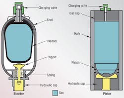
Two designs of accumulators are widely used in hydraulic systems — piston and bladder accumulators, Figure 1. Piston accumulators include weight-loaded piston type, spring type, and hydropneumatic piston type. The weight-loaded type was the first used, but is very heavy for its capacity and much larger than modern piston and bladder types. Both weighted and spring types are infrequently found today. Hydropneumatic piston accumulators are now the type most commonly used in industry.
Functional versatility
Energy storage — Hydraulic accumulators incorporate a gas in conjunction with a hydraulic fluid. The fluid has little dynamic power-storage qualities; typical hydraulic fluids can be reduced in volume by only about 1.7% under a pressure of 5000 psi. (However, this relative incompressibility makes them ideal for power transmission, providing quick response to power demand.) Therefore, when only 2% of the total contained volume is released, the pressure of the remaining oil in the system drops to zero.
On the other hand, gas can be compressed into small volumes at high pressures. Potential energy is stored in the compressed gas to be released upon demand. Such energy can be compared to that of a raised pile driver ready to transfer its tremendous energy upon the pile. In the piston type accumulator, the energy in the compressed gas exerts pressure against the piston separating the gas and hydraulic fluid. The piston in turn, forces the fluid from the cylinder into the system and to the location where useful work will be accomplished.
Pulsation absorption — Pumps generate the power needed for use or storage in a hydraulic system. Many pumps deliver this power in a pulsating flow. The piston pump, commonly used for its high pressure capability, can produce pulsations detrimental to a high-pressure system. An accumulator properly located in the system will substantially cushion these pressure variations.
Shock cushioning — In many applications, the driven member of the hydraulic system stops suddenly, creating a pressure wave that travels back through the system. This shock wave can develop peak pressures several times greater than normal working pressures. It can cause objectionable noise or system failure. An accumulator’s gas cushion, properly located in the system, will minimize this shock.
An example of this application is the absorption of shock caused by suddenly stopping the loading bucket on a hydraulic front end loader. Without an accumulator, the bucket — weighing more than 2 tons — can completely lift the rear wheels of a loader off the ground. The severe shock to the tractor frame and axle, as well as operator wear and tear, is reduced by adding an accumulator to the hydraulic system.
Supplementing pump flow — An accumulator configured for storing power can supplement the hydraulic pump in delivering power to the system. The pump stores potential energy in the accumulator during idle periods of the work cycle. The accumulator transfers this reserve power back to the system when the cycle requires emergency or peak power. This enables a system to use a much smaller pump, resulting in savings in cost and power.
Maintaining pressure — Pressure changes occur in a hydraulic system when the liquid is subjected to rising or falling temperatures. There may also be pressure drop due to hydraulic fluid leakage. An accumulator compensates for such pressure changes by delivering or receiving a small amount of fluid. If the main power source should fail or be stopped, the accumulator would act as an auxiliary power source, maintaining pressure in the system.
Fluid dispensing — An accumulator may be used to dispense small volumes of fluids, such as lubricating greases and oils, on command.
Operation
When sized and precharged properly, the piston will not contact either end cap in a piston accumulator, and the bladder will not contact the poppet or be compressed enough to become folded into the top of its body.
Manufacturers recommend precharge pressure for their accumulators. In energy-storage applications, a bladder accumulator typically is precharged to 80% of minimum hydraulic system pressure and a piston accumulator to 100 psi below minimum system pressure. Precharge pressure determines how much fluid will remain in the accumulator at minimum system pressure.
Correct precharge involves accurately filling an accumulator’s gas side with a dry inert gas, such as nitrogen, while no hydraulic fluid is in the fluid side. Accumulator charging then begins when hydraulic fluid is admitted into the fluid side, and occurs only at a pressure greater than the precharge pressure. During charging, the gas is compressed to store energy.
A correct precharge pressure is the most important factor in prolonging accumulator life. The care with which precharging must be accomplished and maintained should be considered when choosing the type of accumulator for an application. If the user is careless about gas pressure and relief valve settings, or adjusts system pressures without making corresponding adjustments to precharge pressure, service life may be shortened, even if the correct type of accumulator was selected. If the wrong accumulator was selected, premature failure is almost certain.
Mounting position
The optimum mounting position for any accumulator is vertical with the hydraulic port down. Piston models can be horizontal if the fluid is kept clean. When solid contaminants are present or expected in significant amounts, horizontal mounting can result in uneven or accelerated seal wear. Maximum service life can be achieved in the horizontal position with multiple piston seals to balance the piston’s parallel surface.
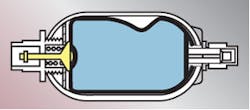
A bladder accumulator also can be mounted horizontally, Figure 2, but uneven wear on the bladder as it rubs against the shell while floating on the fluid can shorten life. The amount of damage depends on fluid cleanliness, cycle rate, and compression ratio (defined as maximum-system-pressure/ minimum-system-pressure). In extreme cases, fluid can be trapped away from the hydraulic end, which reduces output or may elongate the bladder to force the poppet closed prematurely.
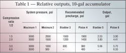
Sizes and outputs Available sizes and capacities also influence which accumulator type to choose. Piston accumulators of a particular capacity often are supplied in a choice of diameters and lengths, Table 1. Furthermore, piston designs can be built to custom lengths for little or no price premium. Bladder accumulators are offered only in one size per capacity, with fewer capacities available.The inherently higher output of the piston accumulator may make it the best alternative when space is tight. Table 1 lists outputs for 10-gal piston and bladder accumulators operating isothermally as auxiliary power sources over a range of minimum system pressures. The differences in precharge pressure, columns 3 and 4, (determined by 80% of minimum system pressure for bladder models, 100 psi below minimum for piston) lead to a substantial difference in outputs, columns 5 and 6.
To prevent excessive bladder deformation and high bladder temperatures, also note in Table 1 that bladder accumulators should be specified with compression ratios greater than 3:1.
Multiple components
Although bladder designs are not available in sizes greater than 40 gal, piston designs are currently supplied up to 200 gal in a single vessel. Economics and available installation space have led engineers to consider multiple component installations. Two of these can cover most high-output applications.
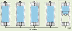
The installation in Figure 3 consists of several gas chambers (often called bottles) serving a single piston accumulator through a gas manifold. The accumulator portion must be sized so the piston does not repeatedly strike the caps while cycling. One drawback of this arrangement is that a single seal failure could drain the gas system. Because gas bottles often are less expensive than accumulators, one advantage of this setup might be lower cost.
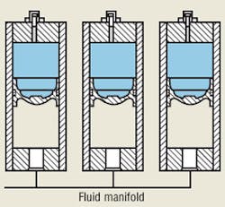
Several accumulators, either piston or bladder design, can be mounted to a hydraulic manifold, Figure 4. If using piston accumulators, the piston with the least friction will move first and occasionally could bottom on the hydraulic cap. In slow or infrequently used systems, this is insignificant.
Gas bottle installations
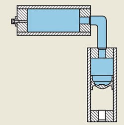
Remote gas storage offers flexibility in large and small systems, Figure 5. The gas bottle concept is often described with this formula: accumulator size minus required fluid output equals gas bottle size. For example, an application that calls for a 30-gal accumulator may require 8 to 10 gal of fluid output. This application, therefore, could be satisfied with a 10-gal accumulator and a 20-gal gas bottle.
An accumulator used with remote gas storage generally has the same size port at the gas end as at the hydraulic end to allow unimpeded flow of gas to and from the gas bottle. The gas bottle has an equivalent port in one end and a gas charging valve at the other. These two-piece accumulators can be configured or bent at any angle to fit available space.
The gas bottle concept is suitable for bladder and piston accumulators. Bladder accumulators require a special device called a transfer barrier at the gas end to prevent extrusion of the bladder into the gas bottle piping.
Again, a piston accumulator should be sized to prevent piston bottoming at either end of the cycle. Bladder designs should be sized to prevent filling to more than 85% or discharging to more than 85% empty. The flow rate between the bladder transfer barrier and its gas bottle will be restricted by the neck of the transfer barrier tube. Because of these drawbacks, bottle/ bladder accumulators should be reserved for special applications.
This article was excerpted from the 2010-2011 Fluid Power Handbook & Directory, and updated by Bonnie Trowbridge, of Lightning Hybrids. Contact her at bonnie@lightninghybrids. com or (303) 519-4144 or visit www.lightninghybrids.com.
For more on accumulators, visit our Tech Zones at http://bit.ly/HPAccumulators and our Fluid Power Basics eBook and our Fluid Power Circuits Explained eBook chapters on accumulators.
