Officials at any of The Walt Disney Company subsidiaries are usually quiet when it comes to describing the technology behind new attractions. The reason is simple: Guests marvel at what goes on in these attractions, and revealing the technology behind the magic might somehow take some of the wonder out of the experience.
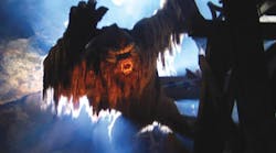
However, company officials were so impressed with what hundreds of craftspeople, technicians, and engineers were able to accomplish with their newest creation — Expedition Everest at Disney's Animal Kingdom, Lake Buena Vista, Fla. — that they tipped their hand. The highlight of Expedition Everest occurs when guests come face-to-face with the yeti, the most highly engineered Audio Animatronics figure ever created by Walt Disney Imagineers. The yeti stands well over 20-ft tall and, counting all motion axes, weighs in at 20,000 lb. As guests zoom past the yeti in a roller coaster train, it shows off 19 axes of lifelike motion by lunging at the train and swiping at it with an arm more than 10-ft long.
The yeti is one of the stars of Walt Disney World's newest permanent attraction, but there's much more to Expedition Everest than the yeti. There's a scaled-down Himalayan mountain range, a mythical village inspired by the architecture of Nepal, and, of course, a roller coaster.
As the story goes
As guests enter the Expedition Everest site, they work their way through a maze of authentic props to give the impression they have entered a Himalayan village. During this initial storytelling portion (everything in the attraction is about storytelling), guests learn that they will embark on a tour through the mountains aboard an old train that formerly hauled tea and is still powered by a steam locomotive.
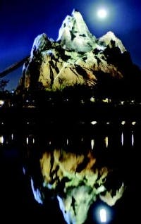
Guests also catch frequent glimpses of Everest towering in the distance. The structure is nearly 200 ft tall, but appears much taller through forced perspective. Forced perspective involves altering the scale at which objects are constructed and painting shadows that create a false sense of depth.
However, guests are repeatedly shown references to the legendary Abominable Snowman — or the yeti, as it is referred to in Himalayan custom. These references become more intense as guests work their way closer to where they will board the roller coaster.
All aboard
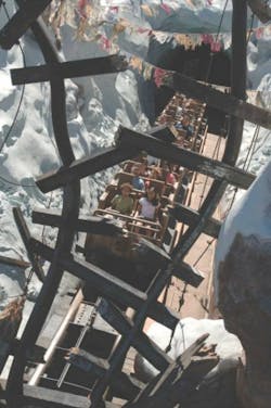
As they approach a loading platform, guests see and hear coaster trains approaching and departing. A train departs as often as once a minute with as many as 34 passengers on each. The coasters are adorned with features that make them appear to be old rusty trains. They have a steel framework with outer bodies made of fiberglass for a combination that is light weight, strong, and durable.
To add realism to the scene, steam is routed to nozzles mounted under the loading platform. This makes it easy to see and hear the steam, but keeps it a safe distance from guests and attraction personnel. A blast of steam is released every time a train stops at the loading platform, giving the impression that the train is, indeed, powered by a locomotive. Steam is again released — and a steam whistle sounds — once the train has been loaded and begins its departure.
It's a switch
Upon departure, the train ascends the attraction's first hill. After climbing a second hill, 112-ft high, the coaster enters a snowy canyon. Something appears seriously wrong. Huge footprints in the "snow" and a distant roar signal that the guests have infringed on the yeti's space. Worse yet, the track ahead is broken and twisted — with nowhere to go except off the track and over a steep cliff!
Lacking any other recourse, the train comes to a halt, then backs up. But instead of heading back into the loading area, it crosses over a switch track that diverts it — backwards — to an alternate route. The coaster continues backward and up through a spiral and eventually stops at the top of an incline. After a brief pause, it rolls forward down the hill, then crosses over another switch track that sends it down an 80-ft drop. The coaster reaches speeds up to 50 mph.
Pneumatics in action
Both switches are thrown by pneumatic linear actuators. But unlike conventional railroad switches, which actuate laterally, these switches rotate on their longitudinal axis, thereby keeping the mechanisms hidden from sight.
Each switch contains four actuators mounted perpendicular to the axis — a pair at the front of the switch and a pair at the rear. One actuator of each pair pushes the switch clockwise while the other pulls it. This setup conserves more space than using one or two large actuators for each switch and more evenly distributes loads. However, these switches are no lightweights; each weighs 20,000 lb. This may seem like overkill, but each switch must support a heavy roller coaster train carrying as many as 34 people.
Once the train has passed completely over the switch, controls unlock a mechanical linkage that holds the switch in place. Controls then command the switch to rotate 180°, then the mechanical lock is reset. The entire sequence occurs in about six seconds. Adding to the challenge is controlling the rotational motion of the switches.
Pneumatic actuators usually shift discretely — they shift from one extreme to the other in an instant. In this case, though, the actuators move through an acceleration ramp, to constant speed, then
through a deceleration ramp. This is done to minimize shock to the system, which extends life. It also reduces noise.
A close encounter
Eventually, the coaster train enters the cave of the yeti. Guests catch silhouetted glimpses of the yeti and hear its roars from a distance. However, the tracks bring them in for an up-close and personal encounter.
John Van Oort, Principal Mechanical Engineer, Show Mechanical Group, Walt Disney Imagineering, Glendale, Calif., explained that the power and precise motion of the application clearly called for hydraulics. He revealed that the total thrust from all 19 motion axes generates nearly 260,000 lb of force.
Rather than try to support the yeti by its own legs, the figure is supported through a steel boom attached at the rear of the figure — roughly at the small of its back.
The figure is securely attached to the end of the boom and becomes a load suspended from a cantilevered beam. The boom also provides two major axes of motion: about 2 ft of vertical motion of the torso, and 5 ft of forward-backward thrust. The boom also supports the hoses and control cables going to the yeti.
More than meets the eye
This setup allows the yeti figure to appear to have even more than 19 axes of motion. Van Oort said both feet and the left hand all are attached to structural framework inside the attraction. Legs are free to bend at the hips, knees, and ankles, and the left arm is free to move at the shoulder, elbow, and wrist. None of these joints are considered motion axes, because they are not powered.
Van Oort revealed, "There are no actuators in his legs or left arm; they just go along for the ride." The thrust and vertical motions of the boom are powered by hydraulic cylinders. The structure consists of stationary framework and a sled, which is pushed forward and backward on ways (plane bearings) by hydraulics.
Van Oort explained, "We reverted back to pre-World War II technology in that the sled runs on sliding ways, like in old machine tools. We have a huge cantilevered load, and the only way to the get the PV [combined pressure and velocity] of the bearings down was to put the sled on ways."
Mounted to the sled is a second hydraulic cylinder that pushes and pulls a second sled up and down. The beam that supports the yeti figure is rigidly attached to the framework of the sled that moves vertically. Therefore, this entire assembly generates two axes of motion.
Bringing the yeti to life
Other motion axes include left-right and fore-aft bending and twisting at the waist; turning, tilting and nodding at the neck; plus fully articulated motions of the shoulder, elbow, wrist, hand, and fingers. The remaining motion axes move the mouth and produce facial expressions.
The cylinders that produce these motions become smaller the higher they are located above the waist. This is because cylinders at the waist must move more mass than cylinders in the neck. For example, cylinders in the waist have a bore of 3¼ in., whereas cylinders in the neck have a 1½-in. bore.
All of these motions are accomplished using hydraulics, except those for the eyes. Pneumatic cylinders were chosen to move the eyes because they are lightweight and space was limited. Servo control ensures lifelike movement of the eyes.
The hydraulic system itself is powered by two variable-displacement axial-piston pumps with pressure compensation set at 3000 psi. Each pump is rated for flow of 60 gpm, but only one pump operates at a time; the other is a standby power source. Flow from the pump is used to charge accumulators, which provide the flows needed to perform the show sequence.
Hydraulic fluid flows from either pump to a bank of eight 15-gal accumulators. These accumulators store pressurized fluid until peak flow of 400 gpm is needed. By storing hydraulic energy and releasing it on demand, the accumulators save energy by allowing the system to be driven by a 60-gpm pump instead of a 400-gpm pump.
Van Oort said designers specified standard components wherever they could. However, strength and longevity for the hydraulic cylinder mounts were well beyond what are found on standard JIC cylinders. Van Oort offered, "Standard mounting configurations just don't handle the kind of duty we put them through. So we started with a standard cylinder and specified extended tie rods at the cap end. Then we made our own mounts — even head trunnions — out of aircraft-quality alloys for high strength and light weight.
"Another concern was the rod seals. We have the cylinders manufactured with extra-long glands and double rod seals. We drain the gland volume between the seals with clear tubing and route it to a place where a maintenance person can monitor flow past the inboard seal." By doing this, personnel can replace a rod seal before it fails. If it should fail, the second rod seal acts as a backup.
Management approval
At the opening of the attraction on April 7 earlier this year, Bob Iger, president and CEO of The Walt Disney Company offered, "Expedition Everest is a shining example of what we do best at Disney — create unique, high-quality, and innovative experiences to delight our guests from around the world." Walt Disney Parks & Resorts Chairman Jay Rasulo added, "This extraordinary expedition is another example of the lengths to which Walt Disney Imagineering will go to research subject matter in developing our story lines."
Click here to watch a video explaining more of the hydraulics technology behind the Yeti..
For more information and images covering the technology behind Expedition Everest, click here to view an article published by our sister publication, Machine Design.


