By R. Paugh and K. Sterry, Pawling Engineered Products
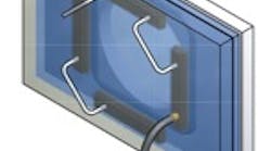
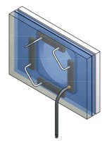
Figure 1. When the blue door slides into place, four inflatable actuators — arranged in a rectangular pattern — expand to seal the door in place.
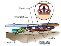
Figure 2. In a soft brake for a glass-cutting machine, inflating the bladder stops the drive belt, which in turn stops the main conveyor belt.
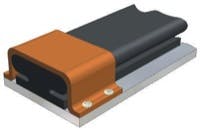
Figure 3. Typical metal end fitting to securely clamp bladder actuator provides enough active actuator length to do the job. Clamped ends will not displace upon inflation and will not contribute to function.
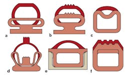
Figure 4. Cross-sectional views of typical inflatable bladder actuators. Retention is usually achieved by installing the actuators into some type of rigid channel. Adhesives may be adequate to hold the actuator in place for less demanding applications. For the footed types, standard mating channels or metal clamps are available.
Many designers overlook the potential of inflatable bladders for actuation applications, but thanks to improved elastomeric materials and new cross-sections, the niche for bladder-type actuators is expanding. Today's inflatable actuators deliver longer strokes — up to 2.5 in. — and many can exert uniform force over their entire stroke. For the right application — typically single-acting, repetitive, short strokes, where positional precision is not required — other advantages include:
- generation of force over a large area
- flexibility to fit in tight locations (It's not unusual to be able to squeeze a bladder into a space where no cylinder or stepper motor would fit.)
- contamination resistance
- simplicity
- light weight
- no metal parts, thus no corrosion
- modest cost
- the economy and reliability of pneumatics, and
- minimal maintenance.
Those are some of the reasons why inflatable bladder-type actuators are being found as workholders, parts positioners, expanding mandrels, and clamps, as well as soft brakes on belt conveyors.
Real-life applications prove successful
Example 1: Inflatable actua-tors serve as automatic door seals for environmental chambers, processing vessels, sterilizers, and flood barriers. Typically, Figure 1, the door slides into place along a track; then the bladder actuators, mounted to the side and arranged to match the outline of the door, expand to press it laterally and seat all the seals. With a single pressurization, the inexpensive actuators exert a surprisingly high, uniform force all around the door.
Example 2: In a web-type glasscutting machine, an inflatable bladder serves as a soft brake that holds the web in place when needed, Figure 2. The machine builder reworked the brake design mainly for gentleness and reliability. Earlier mechanical brakes jerked the belt to a stop, resulting in excessive scrap rates and service calls for the machine as a whole, not just the brakes. The inflatablebladder brake also saved about $500 per machine.
Example 3: Bladder actuators open and close high-pressure control valves in extremely large filtration equipment, where maintenance access is limited. Low air pressure translates into very high forces for reliable operation even under extreme process pressures. In tests, the bladder actuator operated the mechanism against process pressures that actually deformed the valve gate. Plus, there are no loose, moving parts to fail in the actuator mechanism.
These examples illustrate how inflatable bladders can solve certain actuation challenges. All three applications require a force distributed uniformly over a wide area and involve relatively short strokes. They call for relatively low precision, with a very forgiving force-displacement characteristic. And these solutions involve significant savings in installed cost, part count, and maintenance expense.
Putting bladders to work
Designing with bladder actuators begins with the same steps used in conventional air cylinder applications: define the load, the required stroke, the duty cycle, the available mounting envelope, and the ambient conditions. Bladder actuators are not off-the-shelf items, however. Therefore, involving a vendor in the design process will probably move the project more rapidly from concept to hardware.
No standards exist for mounting bladders, so working out the retention method is an important part of the design, Figure 3. Unlike conventional air cylinders, bladder actuators generally exert less force when fully extended. Also, they provide almost no lateral support.
Several different configurations are available to suit a variety of application requirements. The most common type is the footed actuator, Figure 4(a). Although a molded-in foot simplifies mounting, the bulb portion (pressure chamber) expands when pressurized to produce the desired displacement. (This cross section is used in most conveyor stops and part positioners.) The top contact surface also can have a gripping section, Figure 4(b). The gripping cross section helps ensure positive contact in applications involving grit and dirt; the ridge tops stay clean while the grit falls in the grooves between them.
Low-profile cross sections, Figure 4(c), are usually used in hoop-type actuators, where they can be snap-fit into a retention groove.
Convoluted cross sections, Figure 4(d), offer both longer strokes and greater end-of-stroke force than the other types.
Channel-style sections, Figure 4(e), fit into standard aluminum channels with stock dimensions. This configuration provides a large contact area, which can translate into higher forces.
Heavy-duty cross sections, Figure 4(f), can deliver higher forces but with shorter strokes. This actuator usually is installed in a rigid channel, which holds it in place and ensures that all the internal pressure is converted to a vertically upward force.
Inflatable actuators can be molded to almost any cross section — to fit into almost any available envelope. Define the need, and let the vendor help recommend the best solution.
Other considerations
To increase force toward the end of a bladder actuator's stroke, consider a convoluted cross section molded from reinforced material. Another possibility: specify a longer stroke than you actually need, so the actuator never needs to reach the end of its potential stroke. Or mount the actuator in a snug rigid channel, so that all bladder expansion is upward, not outward.
Fast cycling is rarely a problem because the conformable elastomers react almost instantly to changes in pressure and have no dynamic seals to wear out. For higher-speed cycling, specify multiple inflation/deflation points to get more air into and out of the bladder more quickly.
OEM design engineers appreciate the fact that "simpler is better" in most machines. Certainly, inflatable-bladder actuators create real opportunities to simplify short-stroke motion control applications. The key is to not overlook their potential to simplify your next project.
|
Materials Inflatable bladders are available in a variety of elastomers. Any of them can be reinforced with fabric for extra strength, more wear resistance, or better retention of shape. (Reinforcement also can overcome some of the physical limitations of silicone, fluorosilicone, fluorocarbon rubber, and nitrile.) Many of these materials are rated for food grade or nuclear applications because they are contaminant-free and introduce no lubricants or chemical protectants. |
Bob Paugh and Ken Sterry of Pawling Engineered Products, Pawling, N.Y., provided this discussion. For more information, visit www.pawling.com
