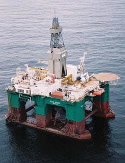
Modern offshore wells were first drilled from mobile platforms that were fixed to the ocean floor over the oil reservoir. These jack-up rigs, which are still in wide use today, are self-elevating. This enables operators to lift the drilling platform out of the reach of waves and tides. Today, jack-ups are generally limited to water depths of a few hundred feet.
For reservoirs in deeper waters, it was not practical to build a support structure to keep the drilling platform on location. Deeper wells required drilling to be accomplished from a floating structure.
The 1960s saw the predecessors to modern day floating drilling vessels. These vessels, unlike jack-up rigs, must have control systems to combat the effects of the ocean: waves, tides, currents, and winds. The motion compensator system is one such system, which uses hydraulics to compensate for wave-induced vertical motion of the drilling structure.
Motion compensator system
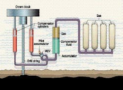
Today, drill ships and semi-submersible drilling platforms use motion compensator systems to allow drilling in water depths to 10,000 ft., while experiencing waves as high as 40 ft. A simplified offshore drilling system is represented in Fig. 2. The motion compensator is made up of:
• compensator cylinders,
• a main accumulator,
• multiple air pressure vessels (APVs),
• an isolation valve, and
• a pilot accumulator.
All of the compensator components are rigidly fixed to the drilling vessel, except for the cylinder pistons that are positioned at mid-stroke and are attached to the drill string (a term used for the entire length of joined sections; also called drill pipe). As long as the MCV is open, fluid flows from the cylinders into the main accumulator when the vessel heaves upward and flows in the opposite direction when the vessel falls into a wave trough. Thus, the drill string maintains its vertical position while wave action moves the vessel.
Pressure in the system is set so that the net weight of the drill string (weight on bit) is at the desired level. For example, assume the desired weight on bit is 5,000 lb. If the weight associated with the drill pipe and other components supported by the compensator cylinders is 1,000,000 lb, and the compensator cylinder control areas equate to 500 in.2, the hydraulic pressure would be set at 1,990 psi, resulting in the desired weight on bit. Pressure of the system is adjusted as drill pipe is added or the desired drilling force is changed.
Pressure in the system will vary as the gas volume changes during a typical wave heave. The pressure will be highest when the rig is on a wave crest, because this is when the gas volume is minimal. In a wave trough, the gas volume will have expanded and the pressure will be at its minimum. These pressure extremes can be somewhat controlled by adding a greater volume of gas.
Another pressure variation is due to fluid pressure losses in the system due to fluid flow. The majority of this variation takes place at the wave mid-point and is minimized by properly sizing the pipes and by utilizing a flow efficient control valve.
The control valve, in addition to being very flow efficient for the weight on bit issue, needs to perform multiple functions for everyday operations. Also, it must automatically isolate the cylinders from the main accumulator should the drill string break. The isolation valve is a system in itself and the heart of the motion compensator system.
Hydraulic control system
The Olmsted Products Co.'s Motion Compensator Valve, or MCV series of valves, has been designed to satisfy all the needs encountered during drilling operations.
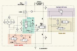
Drilling or stand-by position: During drilling operations, the MCV is held open by system pressure acting on the face of the main gate. As all pilot valves are de-energized in this mode, region C, behind the main gate, is vented to tank. This ensures the gate will remain open (provided there is sufficient system pressure to compress the main valve spring) and allow flow between the main accumulator and the compensator cylinders to compensate for wave-induced motion of the drilling vessel. The highest pressure in the system passes through a filter block and charges a pilot accumulator. The purpose of the pilot accumulator will become clear shortly.
To manually close the MCV, valve V5 is energized. This vents region F (one end of the sensing valve spool) to tank through V5. The pilot accumulator -- working against the other end of the sensing valve spool -- will overcome the spring force, causing the valve to shift. Once the sensing valve has shifted, flow from the pilot accumulator is ported to the backside of the main piston, region C. That closes the main gate. The higher of the pressures in region A or B continues to feed region C, keeping the main gate closed to isolate the compensator cylinders from the main accumulator.
After additional drill pipe is added to the drill string, the MCV is reset to its drilling position by de-energizing pilot valve V5 and momentarily energizing pilot valve V6. This introduces system pressure to regions G and F of the sensing valve thereby hydraulically balancing the sensing valve spool and allowing the spring to return the sensing unit to its normal drilling or stand-by condition. Once the sensing valve has reset, valve V6 is de-energized. Region C is now vented to tank and system pressure reopens the main gate.
Automatic closure operation: As offshore drilling depths have increased, so have the size of the hydraulic systems needed to support additional drill pipe weight. With current technology, offshore drilling rigs may work in up to 10,000 ft of water. The drill pipe on these systems may extend an additional 25,000 ft into the ocean floor. During drilling operations, drill pipe joints, or the pipe itself, can fail or break. In such an extreme event, a hydraulic system that was supporting the weight of 35,000 ft (say, 1,000,000 lb) could end up only having to support 350 ft of pipe, or about 10,000 lb. The pressure in the system of 1,990 psi, which yielded the desired drilling weight on bit, is now left to explosively discharge into the compensator cylinders. If the cylinders are allowed to accelerate to their full extension, the result could be catastrophic damage to the motion compensator system or the derrick structure. Limiting the stroke of the cylinders during this event is the task faced by the MCV.
The initial response to a broken drill pipe is an immediate decompression of the fluid in the motion compensator cylinders. This decompression pulse travels at the speed of sound through the fluid, through the MCV, and back to the main accumulator. When the pulse reaches the main accumulator, the gas behind the separator in the accumulator expands, resulting in flow from the accumulator. It is during this pressure pulse that the MCV is designed to automatically close due to a momentary or sustained loss of pressure in region B relative to the pressure stored in the pilot accumulator.
As the pressure drop pulse passes from the cylinder through the valve, inevitably a momentary loss of pressure will occur in region B of the MCV. Region F will also see this pressure drop because it is linked to region B through check valve V14. The pilot accumulator is charged to the highest system pressure through a 0.040-in. orifice. The accumulator pressure will then exceed the pressure in region F, causing the sensing valve to rapidly shift, which, in turn, will cause the main gate to close. It is imperative that the main gate be closed before the main accumulator starts to deliver fluid back to the MCV, because this will close V14. To ensure that region F is fully vented, the sensing valve was designed so that region F connects directly to tank after an extremely short movement of the sensing valve spool. Pressure in region B will increase above the highest system pressure due to the water hammer effects of flow from the main accumulator being dead headed at the main gate. To prevent this high pressure from re-opening the control valve, the same high-pressure fluid is directed behind the main gate. Note that the sensing valve operates exactly the same whether the main gate is manually or automatically closed. Both types of closing require a pressure decrease in region F. One is by energizing pilot valve V5 and the other is automatic. Utilizing the same operating method to isolate the compensator cylinders was a critical design goal.
Because the automatic feature is so critical, the heart of the MCV system is energized as frequently as possible to verify that the components are free and functioning as designed. Because the valve has been designed to automatically close on the pressure drop pulse, the main gate will be closed prior to significant amounts of flow being introduced to the compensator cylinders, limiting the cylinder travel to mere inches.
The motion compensator is only one example of compensator systems used on offshore rigs today. Each system has different requirements, which require different controls to accomplish the tasks of everyday operations. Bypass valves to equalize pressure before opening the main gate, relief valves to vent pressure from the cylinder to the accumulator side of the isolation valve (in the event that the cylinder pressure rises above a safe value), pneumatic actuation, and electric actuation all are options called for by offshore operators.
Craig LaFave is offshore project manager and Dudley Smith is president/general manager for Olmsted Products Co., Traverse City, Mich. Contact them by phone at (231) 929-1660 or visit the company's website, www.olmstedproducts.com.
