Trouble-free use of fluid power cylinders and their ability to serve and remain leak-free depends, in large part, on properly mounting the component for the particular application. The designer must determine the loading the cylinder will experience and mount it accordingly.
The National Fluid Power Association, NFPA, has standardized on a number of dimensions for square-headed tie rod cylinders to promote cylinder interchangeability between manufacturers. Part of this standardization program includes cylinder mounting styles, which generally provide:
• straight-line force transfer with fixed mounts that do not absorb force on the centerline of the cylinder, and
• pivot force transfer with pivot mounts that absorb force on the centerline of the cylinder and allow the cylinder to change alignment in one plane.
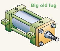
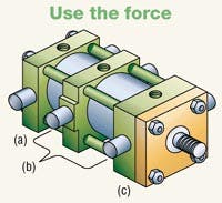
Straight line — Cylinders with fixed mounts that absorb the force on the centerline of the cylinder are considered the best for straight line force transfer. Tie rods extended, flange, or centerline lug mounts are symmetrical and allow the thrust or tension forces of the piston rod to be distributed uniformly about the cylinder centerline. Mounting bolts are subjected to simple tension or shear without compound forces; when properly installed, cylinder bearing sideloading is minimized.
Cylinder tie rods are designed to withstand maximum rated internal pressure, and can be extended at either end and used to mount the cylinder. When the tie rods extend at both ends of the cylinder, one end can be used for cylinder mounting and the opposite end can support the cylinder or be attached to the machine members.
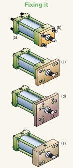
Flange mounts also are extremely good for straight line force transfer applications. Three standard styles are head (rod)-end rectangular flange, head (rod)-end square flange, and a larger and thicker rectangular head with its own mounting holes; the same three versions are available for the capend of the cylinder. Selection of a flange mount depends partly on whether the major forces applied to the load result in compression or tension on the piston rod.
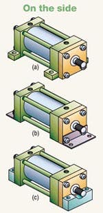
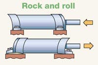
Straight line, force not absorbed — Side mounted cylinders do not absorb force along their centerlines. These mounting styles have lugs on the end closures and one style has side-tapped holes for flush mounting. The plane of their mounting surface is not through the centerline of the cylinder; for this reason, side mounted cylinders produce a torque moment as the cylinder moves the load. This moment tends to rotate the cylinder about its mounting bolts. If the cylinder is not well secured to the machine, or the load is not well guided, side loads will be applied to the rod gland and piston bearings.
To avoid this problem, side mounted cylinders should have a stroke length at least as long as the bore size. Shorter stroke, large bore cylinders tend to sway on their mounts with heavy loading especially with side lugs, end lugs, and end angle mounts.
Side mount cylinders depend wholly on the friction of their mounting surfaces in contact with the machine to absorb the forces the cylinder produces. The torque applied to the mounting bolts should equal that of the tie rod torque as recommended by the manufacturer.
For heavy loads or shock conditions, side mounted cylinders should be held in place with a key or pins to prevent shifting. A shear key — consisting of a plate extending from the side of the cylinder — can be supplied with most cylinders. It should be placed at the proper end to absorb the major loading — that is, at the rod end with the load in tension and at the cap end with a thrust load. This method may be used where a keyway can be milled into a machine member. The key takes shear loads and provides accurate alignment of the cylinder.
Pivot force transfer — Cylinders with pivot mounts that absorb force along the centerline should be used when the actuated load travels through an arc. There are two ways to mount a cylinder so it will pivot during the work cycle: clevis mounts or trunnion mounts. Pivot mount cylinders are available with cap fixed clevis; cap detachable clevis; cap spherical bearing; and head, cap, and intermediate fixed trunnion. Special trunnion assemblies are also available, such as gimbal mounting, which allows the rotation of an object about a single axis.
Pivot mount cylinders can be used in tension or thrust applications at full rated pressure, except that long stroke cylinders in thrust applications are limited by piston rod column strength. Clevis or single-ear mounts usually are an integral part of the cylinder cap, although detachable styles are available and provide a single pivot for mounting the cylinder. A pivot pin of appropriate length and diameter to withstand the maximum shear load at rated cylinder operating pressure is included as part of the clevis mount. The fixed clevis mount is the most popular and is used where the piston rod travels a fixed arc in one plane. It can be used vertically or horizontally.
Trunnion pivot mounts also are used when the piston rod travels an arc in one plane. Trunnion pins are designed for shear loads only and should not be used with bending stresses. The support bearings should be mounted as close as possible to the trunnion shoulder faces.
Head trunnion mounted cylinders usually can be specified with smaller diameter piston rods than cylinders with the pivot point at the cap or at an intermediate position. On head trunnion mounted long stroke cylinders, the designer should consider the over-hanging weight at the cap end of the cylinder. To keep trunnion bearing loads within limits, stroke lengths should be not more than five times bore size.
An intermediate fixed trunnion mount is the best. It can be located to balance the weight of the cylinder or anywhere between the head and cap to suit the application. Its location must be specified at time of order because it cannot be easily changed once manufactured.
Installation
• if high shock loads are anticipated, mount the cylinder to take full advantage of its elasticity, and don't forget: the fluid lines are along for the ride, hold fixed-mounted cylinders in place by keying or pinning at one end only
• use separate keys to take shear loads: at the head end if major shock loads are in thrust, at the cap end if they are in tension
• locating pins may be used instead of shear keys to help take shear loads and insure cylinder alignment. Avoid pinning across corners - this can cause severe warpage when a cylinder is subjected to operating temperature and pressure. Such warpage also is imposed on fluid connectors at cylinder ports, and
• pivoted mounts should have the same type of pivot as the cylinder body and the head end. Pivot axes should be parallel, never crossed.
Consider protecting exposed rods from abrasion and corrosion that could destroy the rod surface and, in turn, the rod seal. In especially dirty environments, protect the rod with a cover such as a rod boot or bellows.
Operation conditions
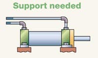
• Cylinders with non-centerline-type mountings tend to change length and sway under load and temperature change. Any rigid tubing connected to a cylinder cap port will be subject to that resulting force and motion. If a cylinder is rigidly plumbed, the question is not whether it will leak, but when.
• Cylinders with non-centerline mountings often require stronger machine members to resist bending, so consider the rigidity of the machine frame. For example, where one end of a cylinder must be overhung, an additional supporting member should be provided.
• In most cases, a layout of the rod-end path will determine the best type of pivot mounting.
* Fixed, non-centerline mounted cylinders with short strokes add another strength problem because mounting bolts will be subjected to increased tension in combination with shear forces.
• Do the major applied forces result in cylinder rod thrust or tension? Cap-end flange mounts are best for thrust loading; rod-end flange mounts are best if the rod is in tension.
• If misalignment occurs between the cylinder and its load, the mounting style may have to be altered to accommodate the skewing movement. A simple, pivoted centerline mounting, such as a clevis and trunnion, compensates for single-plane misalignment. If multiple-plane misalignment is encountered, the cylinder should have self-aligning ball joints on the cap and rod ends of a clevis-mounted cylinder - and fluid-line connections should be able to accept the movement.
