Equipment manufacturers aiming to improve the energy efficiency of their machines tend to focus on using power sources other than pneumatics, such as electro-mechanical or hydraulics. That’s because pneumatics is traditionally viewed as inefficient, due to factors such as leakage and the endemic practice of supplying higher pressure than an actuator requires to perform a task.
But they shouldn’t neglect pneumatics. It’s true there are many potential sources of inefficiency when generating and using compressed air. However, targeted measures can minimize or prevent losses and significantly reduce energy consumption in pneumatically powered machines. Consider the following tactics to avoid dead volumes and optimize the use of compressed air.
Bigger is not always better
On new machines, properly sized pneumatic components are a great start to optimizing energy use. Bigger doesn’t mean better when over-dimensioning leads to unnecessarily high air consumption. It is common practice to assume “when it doubt, go one size bigger.” Or to re-use older designs that were developed without energy efficiency in mind. Oversized components cost more to purchase and operate than properly sized ones. They are also bigger and heavier, an issue when mounting space is at a premium.
Because reducing the cylinder diameter saves on the volume of air consumed each cycle, designers should take advantage of online configuration tools and energy-saving calculators to help size components to meet application requirements.
For example, at a lumber processor we increased a sawmill machine’s output 13% by simply reducing the size of the pneumatics on the sorter gates. Cylinder bore dropped from 3 to 2 in., air valves from in. to … in., and pressure from 100 psi to 60 psi. These seemingly minor alterations effectively increased production speed and produced energy savings of 75% on the machine.
What about OEMs building standard machines for a variety of endusers? Mass-produced machines must be designed and sized to accommodate the user with the lowest available pressure. This usually means specifying larger, more expensive components that increase air consumption. This issue can be partially resolved by regulating the machine’s supply pressure down to the design pressure.
Operators commonly increase supply pressure on regulators in hopes of improving performance, but this ends up wasting significant amounts of money in air and operating costs for no actual benefit – if components are sized correctly. It is important to monitor and ensure machine pressure is within minimum and maximum limits to avoid wasting energy.
Pressure regulation
Lean-manufacturing best practices eliminate any waste that does not add value to a product or process. Pneumatics frequently wastes energy when too much pressure means actuators produce more force than required. This can be overcome with intelligent pressure regulators in pneumatic cylinders that control when to exert energy and when to conserve it. Applying the exact amount of pressure each task needs can produce energy savings of up to 40% in many cases.
Also, pressure regulators that permit “reverse-flow” and mount between a valve and cylinder are becoming increasingly common. They’re usually more economical and easier to install than traditional sandwich pressure regulators. Many standard in-line regulators do not have this capability and require a check-valve in parallel to accommodate reverse flow.
Many applications have either a “push” or “pull” load, but not both. Yet most often machines use the same pressure for both extend and retract strokes, which is extremely inefficient.
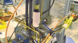
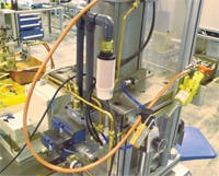
For instance, take the case of a pneumatic cylinder used in a press-fit assembly operation. Pressing the part required 100- psi cylinder pressure, and 100 psi was also used to retract the unloaded cylinder – even though retraction required <10 psi. Adding a pressure regulator between the valve and cylinder port reduced retract pressure to 10 psi – a 90% reduction. The machine used 38% less energy per cycle, and the savings paid for the new components in approximately 2100 cycles.
In addition to press-fit processes, applications that use rodless or lifting cylinders, such as automotive assembly elevators, typically can benefit from non-load stroke pressure regulation. In general, the larger the cylinder the larger the efficiency gain. The key: be on the lookout for motions with a sizeable difference in the force required for each stroke direction.
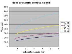
Energy savings are just one benefit of pneumatic pressure regulation. Because cylinder speed is governed by the rate at which air exhausts on the nonload side of the piston, reducing the non-load pressure permits higher piston speed on the working stroke. This decreases cycle time. Other advantages include reductions in shock, vibration, and noise as well as longer life for components and the machine itself. And if there are leaks in the system, reducing the air pressure inherently reduces the amount and cost of leakage.
Regenerative circuits
For applications that require high pressure for both push and pull strokes, a regenerative system can produce air savings of up to 50%. Rather than installing a pressure regulator to cut air consumption, air in the load side of the cylinder recirculates back into the other side of the cylinder to do work.
One example involves crust breaking in aluminum processing. Large cylinders mount vertically over vats of molten metal with the rods facing down. Tooling attached to the rods is fairly heavy, so high air pressure is needed to retract the cylinder rods. High pressure is also required to extend the cylinders even though gravity helps. That is because high force is needed towards the end of the stroke to break the crust covering the liquid aluminum.
The same characteristics apply in clamping applications which only require high force near the end of the working stroke. Regenerative valve circuits divert air exhausted from the cylinder stroke with gravity assist and use it to charge the opposite end of the same cylinder when out-stroking.
Optimize vacuum applications
Machines that use vacuum generators (ejectors) typically consume more energy than necessary to perform material handling tasks. In conventional systems, a solenoid valve that supplies compressed air energizes the vacuum generator, and vacuum cups contact the product itself. As long as vacuum cups hold the component, the vacuum generator consumes air. Because vacuum cups wear over time, vacuum generators tend to be over-sized to accommodate leakage. This consumes more compressed air and increases equipment operating cost and noise.
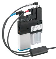
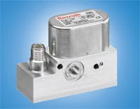
To remedy this, consider retrofitting the machine with a vacuum generator that has an automatic air-savings option. These generators, such as the ECS series from Bosch Rexroth, monitor vacuum levels with an integrated sensor. When the generator switches on, the vacuum valve opens only until the system reaches a preset vacuum level. As long as the vacuum stays within the programmable hysteresis range, the valve automatically de-energizes and closes, consuming no compressed air. If vacuum drops below the preset limit (due to leaks or disconnection), the solenoid valve re-energizes to maintain the preset vacuum.
Vacuum generators with air-saving controls are easy to install or retrofit, and they can greatly reduce air consumption and operating costs. Other tangible benefits include significant noise reduction on equipment because the vacuum valve energizes less frequently. Further, how frequently the vacuum sensor activates gives an indication of both cup wear and overall system efficiency.
Minimize leaks
Leaks are costly. For end users seeking to improve the efficiency of pneumatic systems, the low-hanging fruit is finding and fixing leaks.
Valves and deteriorated seals are two common sources. Some valve designs, such as lapped spool valves with metal sealing, have inherent internal leakage up to 700 cc/min even when new. Leakage is constant as long as air is supplied to the valve. Switching to comparable valves with soft seals can cut leakage to between 10 and 30 cc/min.
Another cause of leakage in industrial applications is when seals are attacked by chemicals in the air system. The pressure regulator is typically the first component to fail due to incompatible contaminants in the air supply. If its Buna seals deteriorate, consider installing an active-carbon filter bed or lubricator, or switching to devices with HNBR, Viton, PTFE, or polyurethane seals.
Automatic air reduction control is another means of significantly increas ing machine efficiency. Most installations have no automatic means of shutting off air to idle machines, and having maintenance personnel individually turn off air to specific machines is generally too cumbersome. And some subsystems require pressure even after the machine is turned off, such as air bearings, air gauging, and cleaning. Frequently, however, a lower supply pressure or high pressure for short durations can satisfy these functions.
For machines that do not run around the clock, an automatic air reduction control package reduces supply pressure and air consumption when the plant is not operating. Typically, the system can be overridden if higher pressure is required during off-hours.
Decentralize the air supply
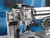
Centralized valve manifolds have the reputation of being cumbersome, they usually require long air lines, and they consume a lot of energy. Manufacturers now offer decentralized valve units made of engineered polymers that are small, light, chemically-resistant, and can mount right next to an actuator.
This direct connection of valves and cylinders eliminates pressure losses and volume of long lines from the control cabinet to the pneumatic drive. Valve/actuator units can reduce tubing connections by 50% and result in energy saving of 35%. Decentralized systems can also yield faster response times and higher cycle frequencies.
In addition, valves and manifolds are available with IP69K protection and with sanitary design and materials suitable for food processing. This eliminates the need to house pneumatic valves in remote stainless-steel enclosures with long tubes running to the actuators.
The bottom line
On a plant-wide level, steps to boost energy efficiency are certainly possible. But users should work with their equipment suppliers to consider what steps to take at the machine design level. Energy comprises more than half the total cost of ownership in pneumatics today, and a constructive evaluation of pneumatic applications quickly pays off. Every application is different, and the overall machine and types of components influence the potential for energy savings. Pneumatics should be part of the strategy to boost energy efficiency in industrial machinery.
Thomas Dwyer is Application Support Manager, Bosch Rexroth Corp., Pneumatics Div., Lexington, Ky. For more information, e-mail [email protected] or visit www.boschrexroth-us.com.
|
Efficiency tactics • Precisely size components to match the application. |
