Today’s economic climate is forcing machine and vehicle builders to improve the productivity, efficiency, and longevity of the equipment they make and sell. As a result, operations across many industries are now demanding hydraulic cylinders that move faster, generate higher forces, and last longer than ever before.
In addition, societal demands are increasing requirements for cylinders that operate with high efficiency and little or no leakage – to diminish the environmental impact.
These conditions mandate high-performance sealing systems that control leakage, lower friction, and minimize costs over the expected life of the cylinder. This requires careful design and collaboration among cylinder and sealing-system engineers.
This article examines seal design considerations related to higher operating speeds. In a future installment, we’ll look at how the push for higher pressures and longer life affect seal design.
Moving faster
Fast cylinder movement can have a variety of meanings, including:
• High extension or retraction rates.
• More cycles in a given time.
• Less dwell time between extension and retraction.
• Higher acceleration and deceleration rates.
All these conditions affect the seals. They can generate more friction and wear, cause pressure buildup, and lead to unforeseen dynamic events that can play havoc with the sealing system. Here’s a closer look at each.
Higher heat
As hydraulic systems move faster, they tend to generate more heat that can adversely affect seals and cylinders. Heat sources include:
• Dynamic effects between the seals and bearings and the rod and housing, which typically worsens with higher velocities.
• Valves and other control units that shift faster or convey more fluid in a shorter time.
• The fluid and surrounding hardware, which has less time to cool.
• Fluid breakdown or viscosity changes.
• Hose and tubing routing.
• Braking devices that give quick, accurate stopping.
High temperatures can alter seal friction, leakage, and durability. For cylinders, heat can affect position control, energy consumption, life, and overall costs. For instance, seal performance can change with temperature, causing the cylinder’s feedback system to generate overshoot or undershoot and affect positioning. Changes in fluid viscosity and seal characteristics mean the pumps must work harder, reducing efficiency. Cylinder life is directly linked to seal life, which tends to degrade as temperatures rise. And downtime, lower performance, and higher energy consumption all affect costs.
To minimize the effects of heat, cylinder manufacturers should ensure proper alignment to uniformly load the sealing system, minimize external heat sources, cool the fluid, and ensure adequate fluid exchange near the seal.
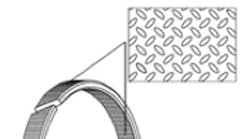
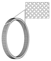
Seal suppliers should investigate bearings and seals. For bearings, ensure the design, material, and location relative to the seals will handle the heat, limit additional heating from bearing friction, support the seals, and potentially aid in forming a fluid film under the seal. For example, some polymer bearings use a “teardrop” pattern to help form such a film.
For seals, primarily investigate high-temperature materials and designs. A secondary effort would be to decrease friction to lower temperature near the seal. Ways of doing this are to reduce seal contact stress, change the seal footprint, adjust fluid film under the seal, or change the material.
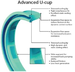
One example that incorporates all four changes is a new U-cup from Trelleborg. The design increases temperature capability and lowers friction compared to standard U-cups. It also contains a micro-structure combined with back-pumping channels on the dynamic seal slide segment that ensure a constant lubrication film underneath the seal sliding surface and back-pumping across its entire pressure range. This reduces friction and temperature near the seal. Tests have shown that at higher speeds, the Ucup produces less friction compared to other designs.
Although seal suppliers and cylinder manufacturers can work independently to minimize effects of heat generated from fast-running systems, a team approach works best. The sealing system is more than just seals and bearings. It also encompasses component layout, mating hardware, and operating conditions. Here are some examples of steps that both seal supplier and cylinder manufacturer can take together to handle the heat.
• Ensure proper surface finish. Inappropriate surface finish does not allow an adequate fluid film under the seal and thus generates heat. Too smooth a surface does not permit sufficient fluid film under seals. Too rough causes the seal to initially ride on the surfacefinish peaks, and that quickly causes surface and seal wear. This can also increase friction and leakage, and reduce life.
• Ensure proper rod hardness and surface coating. Hardness and coatings have to be adjusted with surface finish. Too soft a rod or insufficient coating thickness will potentially let the seal alter the surface finish. Too hard of a surface may damage the seal.
• Maximize bearing load distribution. Unit loading that’s too high adds to system heat and limits life. Consider the overall packaging envelope to determine proper bearing width and spacing.
• Change the lubrication pattern underneath the bearings. Adding grooves, cavities, patterns, or splitting the bearing will alter lubrication paths. This can reduce frictional heat from the bearings and help ensure the seal rides on an adequate fluid film. However, bearing costs may increase.
• Understand bearing spacing relative to the seals. Unsuitable bearing locations will not provide adequate support for proper alignment. This increases local loading and temperature of the seals.
• Understand seal component layout and its affect on fluid-film thickness. To reduce heat, seals must ride on a thick fluid film which can be pumped back into the system. Too few or inappropriate components can increase leakage, friction, or pressure buildup, while too many components will increase costs and frictional heat.
• Review fluid conditions. Changes in viscosity and potential fluid breakdown affect the fluid film on which seals ride. Too thin a film results in higher friction and heat. Too thick a fluid film may result in excess leakage.
• Understand potential hardware dynamics. Thermal expansion can cause hardware to balloon and high temperatures can make components bend. Designers must account for how these factors change the seal contact stresses, which affects the fluid film thickness. Other heat-related hardware dynamics include softening of the bearing supports or the bearings themselves. This limits bearing load capability and can mean uneven unit loading.
Wear resistance
Higher wear related to faster cylinder movement can be caused by:
• The time-related dynamic effect of seals and bearings in contact with the rod and housing.
• Poor lubrication.
• Increased impact of contamination in the system.
• Heat-related changes to material properties.
Similar to the above discussion, wear adversely affects a cylinder’s position control, energy consumption, life, and overall cost; and sealing system friction, leakage, and life. And wear severe enough to damage seals and mating hardware will drive up costs.
As mentioned previously, ensuring proper cylinder alignment and cooling helps reduce wear. Also, minimal system contamination reduces the abrasive impact particles have on seals; tighter tolerances narrow the variations which the sealing system must handle; and limiting conditions such as hold-underpressure and dithering, where the seal operates under poor fluid-film conditions will all have a positive effect.
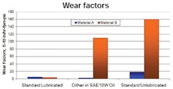
The same basics with regard to heat also apply to reducing seal wear. However, when reviewing designs and materials, wear resistance instead of temperature capability is the desired characteristic. Designing for wear is significantly more complicated, as wear is a function of surface finish, running surface hardness, fluid, material, design, velocity, temperature, and loading. Engineers must consider all these factors when testing to create meaningful data on wear characteristics of materials and products.
For instance, the accompanying graphic shows some typical test results, and how the choice of material may change based on operating conditions. Review test data with regards to product design, system component layout, operating conditions, and mating hardware – as the seal material is just one part of an effective sealing system.
The same recommendations to combat heat also apply to reducing wear. But designers must place added emphasis on understanding sealingcomponent layout and its effect on fluid-film thickness. A thicker film reduces wear as seals ride on top of the fluid, but it increases the potential for leakage. Seal suppliers often add components to increase fluid film thickness and control leaks, as well as ingression rings to reduce the impact of contamination on the seals.
Cylinder manufacturers, on the other hand, want to minimize the space and cost for sealing components. Thus, seal suppliers and cylinder manufactures must balance leakage versus wear versus cost to meet desired performance and price targets.
Pressure buildup
Pressure buildup can affect the seals in fast-running systems. Causes include short-duration buildup (pressure spikes) due to slow valve response, closing action of the valves, and lack of appropriate accumulators, or from letting the fluid film pass under the seal but not re-enter the system, as hydrodynamic pressure to feed back fluid is insufficient. Resulting effects on cylinders include:
• Load limitations. Seals cannot handle the pressure required to move the load.
• Position control. Frictoin is changing in the seal ing system, and this affects the feedback loop and causes the potential for overand undershoot.
• Life. Pressure buildup can extrude seals and increase wear rate, causing premature failure.
• Energy consumption. Higher friction demands more energy to move the cylinder.
• Cost. Higher energy consumption and downtime increases costs.
• Safety. There is a potential for residual pressure between seals when the machine shuts off.
Cylinder manufacturers can minimize pressure spikes by ensuring valves operate at the proper speeds and have smooth closing actions. Also maintain appropriate pressure damping with accumulators and pressurerelief valves. Moving the source of pressure pulses away from the sealing system also helps.
Sealing-system designers can counter pressure buildup in various ways. Systems with rapid pressure buildup can minimize the impact by reducing pressure before it reaches the primary seal, such as using buffer seals.
Several methods mitigate pressure buildup between seals.
One is to increase contact stress between the seal and moving component and prevent leakage that causes pressure buildup. Higher contact stress eliminates hydroplaning which lets fluid get past the seal, but results in thinner fluid films that may increase heat and wear. If the material and design can handle higher temperatures and thinner fluid films over the expected life of the cylinder, then this is not a problem.
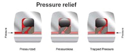
Another alternative uses pressurerelieving seal designs. As the name implies, it vents built-up pressure without component damage. The accompanying graphic shows a seal with an integrated check valve that automatically releases inter-seal pressure that exceeds system pressure.
A third option increases strength by changing the design, material, or adding support materials such as backup rings. Use caution with this route as it can complicate assembly and have other adverse effects, such as increased frictional heat and wear of mating hardware.
Other ways to minimize the effects of pressure buildup include:
• Ensure proper surface finish, rod hardness, and surface coating. An inappropriate finish can let too much fluid pass under the seal, leading to pressure buildup between seals. Conversely, it may mean the seal rides on an insufficient fluid film causing excessive friction and wear.
• Understand sealing system component layout. Adding or substituting components such as a buffer seal or pressure-relieving seal may reduce pressure buildup. However, packaging envelope limitations and cost could be the trade-off. Adding fluid volume between seals could also reduce pressure buildup. But understand the duty cycle to ensure that pressure can be relieved and does not build up over time.
• Check fluid conditions. If fluid viscosity is too high, fluid may pass under the seal and not reenter the system. Alternatively, low-viscosity fluid may prevent pressure buildup between seals but might not provide enough lubrication, increasing heat and wear.
• Review assembly. High-strength materials, which are less pliable, and extra components such as backup rings may be the preferred method to combat pressure buildup. However, this complicates assembly.
Dynamic events
Fast-moving cylinders can produce abrupt starts and stops, dithering, ballooning, vibration, and noise. Sources include system plumbing (valves and accumulators), filters, connectors, and the momentum of fast-running systems. These impact cylinder life, position control, energy consumption, and cost. Good system layout and the right valves, accumulators, and filters can minimize start/ stop and dither effects.<
For vibration and noise, concentrate on vibration damping and noise absorption; minimizing misalignment for uniform seal loading; and tighter tolerances, which minimize variations for which the seals must compensate.
Seal suppliers can also alleviate dynamic effects in these areas:
• Ensure that sealing components handle a wide range of tolerance conditions, including ballooning.
• Ensure adequate fluid film under the seal in all conditions through design, optimum contact stresses, and seal layout.
• Ensure designs and materials are strong enough to handle high impact or dithering conditions. Specially formulated materials are designed to operate in dithering environment s without affecting the mating hardware.
And design factors such as proper surface finish and rod hardness ensure an adequate fluid film that lets the seal handle all operating conditions.
Good bearing load distribution helps damp noise and vibration, while excessive loads may add to the problem. Unsuitable bearing locations means inadequate support and alignment issues, resulting in higher unit loading of sealing components, the potential for vibration and noise, and inability of the seals to track the dynamic surfaces in all conditions.
Finally, understand sealing system component layout and the effect on fluid film thickness. Striving to have an adequate fluid film under the seal in all conditions lets the sealing system better cope with the dynamic effects of starting/stopping, dithering, and vibration/noise.
For more information, contact Trelleborg Sealing Solutions, Fort Wayne, Ind. at www.tss.trelleborg.com/us.
