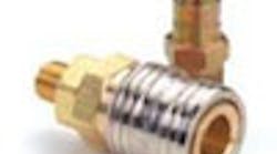
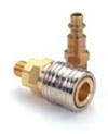
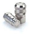
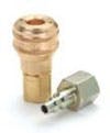
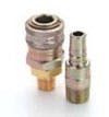
More than a dozen common designs of quick-acting couplings exist. Here is a brief look at eight of the most popular locking mechanisms used in fluid power applications.
Regardless of the manufacturer, all quick-acting couplings have some elements in common. All have two parts: a plug and a socket. The plug is the male half and the socket is the female half. When connected properly, these parts seal and lock the joint effectively to contain internal pressures and resist any tensile forces that tend to pull the joint apart. The parts are easily disconnected without tools by disengaging a locking mechanism and separating parts.
4. Roller-lock couplings use locking rollers or pins spaced end-to-end in grooves or slots around the socket's ID. As the plug is inserted, a ramp on the plug OD pushes the rollers outward. Once the plug is inserted the prescribed distance, the rollers slip into a retention groove on the plug's OD. Retracting the locking sleeve, which allows the ramp on the plug OD to move the rollers outward, releases the plug.
5. Bayonet couplings rely on the familiar twist locking arrangement and are widely used in a variety of applications, especially in plastic couplings for lighter-duty pneumatic equipment. To join the coupling halves, lugs on the OD of the plug engage slots in the socket sleeve as the plug is pushed into the socket. A quick turn locks the lugs into position. Turning the plug in the opposite direction allows the halves to be pulled apart.
7. Cam-lock couplings lock the socket to the plug when two external levers are folded back against the sides of the socket. These are most common in larger sizes and generally require more spaces than comparable couplings of the same size. Moreover, the locking mechanism can wear if lines are connected or disconnected frequently, which can allow leakage.
8. Multi-tube connectors are the fluid equivalent to electrical Cannon-style connectors. They quickly and easily connect or disconnect several tubing lines, while maintaining a correct line orientation and discrete flow paths during reconnection.
Photos courtesy of Hansen Couplings Div. of Eaton Hydraulics Group.
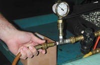
Where should quick-acting couplings be used?One common application is in assembly workstations, where a worker may have to rapidly switch from impact wrench to drill to riveter. With one quick-acting coupling half on every tool and the mating half on the air line, tool changing is accomplished in seconds. Without the couplings, separate air lines would be needed for each tool; the mass of tools and lines would clutter the workstation and could slow down production.
On hydraulic test stands, quick-acting couplings eliminate bottlenecks by slashing the time required to test each assembly. Just a quick push/pull, and the assembly is ready to test. In contrast, testing time would skyrocket if technicians had to tap into systems using fittings and a wrench for each test procedure.
Selection considerations
Before selecting a coupling, questions must be answered regarding its expected performance. These questions focus not only on the coupling, but the fluid medium as well. For example, what fluid will flow through the coupling? Characteristics of the fluid — viscosity, corrosivity, etc. — will influence the type of coupling that should be used. Other questions concerning the fluid deal with temperature (high, low, or wide variation), pressure, and flow rate.
Knowing details on the fluid, questions must be answered about the coupling's construction. How often will the coupling be connected and disconnected? What type and diameter of hose or tubing will be used to contain the fluid? Will the coupling or hose be subjected to abuse such as impact from falling objects, severe vibration, or contamination from the environment?
Once these questions have been answered, a preliminary selection of coupling type can be made: one, two, or no shutoff valves, and the type of connect/disconnect mechanism. Keep in mind that one style may offer the greatest convenience in service, but a different model's lower pressure loss may be more desirable for the application.
