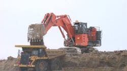
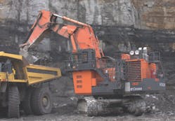
Hydraulic systems in mobile mining equipment are typically exposed to high particle ingression rates. A mine using a Hitachi EX2500 excavator was experiencing premature component failure due to contamination. In the machine’s first 27 months of operation, technicians had to replace four variable-displacement piston pumps (at a cost of $20,000 per exchange or $34,000 for a new one), three swing motors, two drive motors, numerous servo valve repairs or replacements, 42 hydraulic hose related problems, and 16 instances requiring cleaning of contamination sensors.
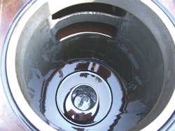
The oil was highly contaminated and suffered excess oxidation after 2255 service hours, so it had to be replaced. Other associated costs included more than 39 hr of unplanned equipment downtime, plus associated maintenance costs. The machine also suffered reliability problems and was approaching the end of its warranty period. The goal was to reduce downtime associated with premature pump failures and minimize costly component repairs or replacements.
Seeking a solution
Fluid cleanliness levels per ISO4406:1999 were consistently monitored from 22/20/17 t o 21/19/15. Based on the criticality of the hydraulic system components and the cost of unplanned downt ime , mine operators set a target fluid cleanliness code of 15/13/10 with a total system cleanliness approach. Each drop in ISO code means the number of particles in the fluid is cut roughly in half, so reducing the 4 μm channel from 22 to 15 would effectively mean reducing the number of particles 4 μm and larger from about 30,000 to approximately 240.
Step 1 — Maintenance practices were implemented to minimize the introduction of contaminant into the system from new hoses. A projectile was shot through all new hoses after they were assembled to remove rubber and metal shavings. Hoses were then flushed to ensure cleanliness, then capped to prevent contamination during storage and handling prior to installation. Training was implemented to ensure that technicians were familiar with the correct procedures to minimize ingression during hose replacement and installation.
Step 2 — The original hydraulic fluid was rated for 4000 hr but had shown signs of oxidation after 1000 hr and was highly oxidized (a total oxidation number exceeding 30) after 2250 service hours. The fluid was upgraded to Mobil DTE 25 to improve component wear protection and reduce the potential of varnishing and deposit formation in hydraulic pumps, valves, and motors.
Step 3 — The original Hitachi return line filter element was made with 10 μm nominally rated cellulose media. Based on the high contaminant ingression rate from the large cylinders and the environment during service, excessive vibration, and dynamic system conditions, the action plan included upgrading from existing 10 μm cellulose media (10 = 1.4) to Hy-Pro 12-μm rated glass media elements (12 > 1000) to flush and stabilize the system. Then a 6-μm glass media (7 > 1000) would be installed to achieve and maintain the target fluid cleanliness.
The housing inlet port was found to be causing damage to the pleated media, compromising the element’s efficiency. A perforated flow deflector was added to the new element to protect it from damage in service. Inspection of spent elements revealed signs of abrasion and that the original elements were not sealing properly with the housing, so gasket seals were added. The original element had no seals to prevent fluid bypass.
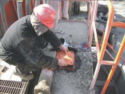
Step 4 — Oil sampling procedures were standardized, and personnel were trained on new procedures to ensure more consistent f luid s ampl ing. The mine continues to use bottle sampling as its primary means of oil analysis. Ideally, however, sampling ports would be installed in several locations to allow on-line particle counting to minimize sampling error from bottle background contaminat ion, dirty sample valves or ports, com. and potential exposure to airborne contamination during sample collection.
Sample ports provide a place for contamination to accumulate, and on-line particle counting allows determining when the sampling port is free and clear of particle deposits that can artificially inflate counts. With an on-line particle counter connected to a sampling port, the counts will trend downward as the port is flushed. Once the counts have stabilized, the port is clean and ready for sampling. The flushing interval can range from several seconds to several minutes. Proper sampling port type, location, and on-line particle counting offer the most accurate indication of fluid cleanliness.
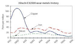
The result — The impact of the fluid change was seen almost immediately. Copper levels, indicative of pump shoe wear, dropped by an average of 70%, and overall component wear metals also dropped. The fluid service life was extended to 17,000 hr, far exceeding the OEM rated fluid service of 4000 hr. The 12-μm flushing element was replaced after 50 hr of service, then the 6-μm element was installed. The result is better than the target cleanliness of 15/12/9.
Extending interval between element changes is typical when upgrading from cellulose to high efficiency glass media elements. So after the runaway contamination problem was under control and a cleanliness equilibrium was reached and verified by oil analysis data, the filter element replacement interval was increased from 500 hr of operation to 1000 hr.
Furthermore, the original equipment contained no differential pressure gauges or pressure gauges on or near the filter assemblies. A device had been installed but was damaged in service. Attempts are underway to install differential pressure gauges to help achieve maximum filter element life.
Overall hydraulic fluid cleanliness levels have greatly improved by reducing contamination ingression and removing more contaminants through filtration. The substantial costs associated with component wear have also been drastically reduced over the past four years. This resulted in the elimination of four pump replacements, 39 hr of shovel downtime, and a 400% increase in hydraulic fluid life.
For more information on hydraulic filtration, contact Hy-Pro Corp., Fishers, Ind., at (317) 849-3535, or visit www.filterelement.com.
|
A total systems cleanliness approach
Developing a total system cleanliness approach to control contamination and care for fluids from arrival to disposal will ultimately result in more reliable equipment operation and save money. The steps to achieve total systems cleanliness include: 1. Evaluate and survey all hydraulic and lubrication systems. 2. Establish an oil analysis program and schedule. 3. Insist on specific fluid cleanliness levels for all new fluids, and/or filter all new fluids upon arrival and during transfer. 4. Establish a baseline and target fluid cleanliness for each system. 5. Seal all reservoirs and bulk tanks. 6. Install high quality particulate and desiccant breathers to keep dirt and water out of the hydraulic fluid. 8. Use portable or permanent off-line filtration to enhance existing filtration. 9. Enhance air and liquid filtration on existing systems wherever suitable. 10. Make a commitment to fluid cleanliness. |
