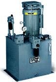
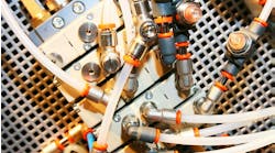
Hydraulic power units provide the muscle and precise control for this typical automotive transfer line.
When specifying components for a hydraulic power unit, the prime mover is sized based on torque, speed, and power requirements of the hydraulic pump.
This is fairly straightforward for electric motors because they generally have a starting torque that far exceeds running torque. Often, though, designers specify motors sized larger than necessary. This results in wasted energy because the motor operates at less than maximum efficiency.
The cost of electricity to operate an electric motor over its entire life span generally is many times that of the cost of the motor itself. Therefore, sizing the motor motor correctly for a hydraulic power unit can save a sizable amount of money over the life of the machine. If system pressure and flow are constant, motor sizing simply involves the standard equation:
hp = QP / 1714EM
where:
hp is horsepower
Q is flow in gpm
P is pressure in psi, and
EMis pump's mechanical efficiency. However, if the application requires different pressures during different parts of the operating cycle, you often can calculate root mean square (rms) horsepower and select a smaller, less-expensive motor. Along with the calculation of rms horsepower, the maximum torque required at the highest pressure level of the application also must be known. Actually the two calculations are quite simple.
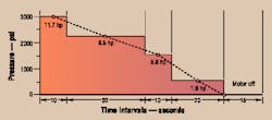
For example, such an application might use a 6-gpm, 3450-rpm gear pump to power a cylinder linkage that operates for an 85-sec cycle. The system requires 3000 psi for the first 10 sec, 2200 psi for the next 30 sec, 1500 psi for the next 10 sec, and 2400 psi for the next 10 sec. The pump then idles at 500 psi for 20 sec, followed by 15 sec with the motor off.
It's tempting to use the standard formula, plug in the highest-pressure segment of the cycle, and then calculate:
hp = (6)(3000) / (1714)(0.9)
= 11.7 hp for 10 sec.
To provide this horsepower, some designers would choose a 10-hp motor; others would be ultraconservative and use a 15-hp motor; a few might take a chance with 7.5 hp. These motors in open dripproof C-face models with feet would list at about $570, $800, and $400 respectively, so there could be savings of $170 to $400 per power unit by choosing the 7.5-hp motor — if it will do the job.
To determine this, first calculate the horsepower for each pressure segment of the cycle:
hp1= 6(2200) / (1714)(0.9)
= 8.5 hp for 30 sec.
hp2= 6(1500) / (1714)(0.9)
= 5.8 hp for 10 sec.
hp3= 6(500) / (1714)(0.9)
= 1.9 hp for 30 sec.
The rms horsepower is calculated by taking the square root of the sum of these horsepowers squared, multiplied by the time interval at that horsepower, and divided by the sum of the times plus the term (toff /F), as indicated in the box at top right.
Substituting the example values into the boxed equation and solving reveals that hprms equals 7.2. Thus, a 7.5-hp motor can be used from the standpoint of horsepower alone. However, the second item, maximum torque, still must be checked before reaching a final decision. The maximum torque required to drive this particular pump will be found at the highest pressure — because the gear pump's output flow is constant. Use this equation:
T = DP / (12)(6.28)EM
where
T is torque in ft-lb, and
D is displacement in in. 3
For this example,
D = (6)(231) / (3450)
= 0.402 in. 3
Then
T = (0.402)(3000) / (12)(6.28)(0.9)
= 17.8 ft-lb.
Because electric motors running at 3450 rpm generate 1.5 ft-lb per hp, the 17.8 ft-lb of torque requires (17.8 /1.5) or 11.9 hp at 3000 psi. This checks out closely enough for the example application. (At other standard motor speeds: 1725 rpm generates 3 ft-lb per hp; 1150 rpm, 4.5 ft-lb per hp; 850, 6 ft-lb per hp.) Now the second criteria can be checked against what the suggested motor can deliver in torque. What is the pull-up torque of the 7.5-hp motor selected? Because the torque is lowest as the motor accelerates from 0 to 3450 rpm, it must be above 11.9 ft-lb with an acceptable safety margin. Note that a motor running 10% low on voltage will produce only 81% of rated pull-up torque: i.e., (208/230) 2 = 0.81. Reviewing motor manufacturers' performance curves will show several available 7.5-hp models with higher pull-up torque. Any of these motors could be a good choice for this application.
Both motor criteria now have been verified. The rms horsepower is equal to or less than the rated motor's horsepower. The motor's pull-up torque is greater than the maximum required.
Multiple-pressure duty cycle for 6-gpm gear pump in example with calculated horsepowers.
Root mean square horsepower:
where: t is the time interval in sec, and F is a constant — 3 for open dripproof motors; 2 for totally enclosed fan-cooled motors.
This article is excerpted from information originally submitted by Ronald R. Gould, CFPE, former vice president of engineering, Advanced Lifts, Inc. St. Charles, Ill.


