By Joseph Urciuoli, MacTaggart Scott & Co. Ltd., North Easton, Mass.
About 20 miles west of Eugene, Oreg. , on the scenic McKenzie River, is the Leaburg Dam. Standing on the dam, you can look down on the water rushing beneath the gate below and see salmon or steelhead trout breaking the water’s surface. But to the Eugene Water and Electric Board, you are standing on a valuable asset that is the key to deriving clean, renewable energy from the water that flows down the valley. The dam is a historical landmark, built more than 75 years ago. It holds back the river at a height of approximately 20 ft.
Raising or lowering the dam’s gates is no easy task. The gates are lifted using chain that is wrapped around the barrel of the gate. As the chain is taken up, the gate — which is fitted with a large pinion gear — rolls up a rack gear fitted to the dam. Each of the three roll gates weighs in excess of 100,000 lb and spans 125 ft. There is also a significant and varying hydrostatic load on the gate, due to its shape.
Off to one side of the dam, water is diverted into a canal and flows down the side of valley until the river has dropped to 100 ft below. The water then enters a penstock that leads into turbines that generate up to 15,000 kW of electric power.
Getting up to speed
In order to meet strict Federal re-licensing requirements, the dam has undergone a technological transformation, where instrumentation constantly monitor the river’s flow. This information is fed into a central computer that calculates the precise gate openings to maintain a minimum required downstream flow of 1000 ft 3/sec within a 20 ft 3/sec tolerance. To achieve the required accuracy, the gates must be positioned to within ±18 in.The original hoist mechanism was an electric 5-stage open gear design that drove a sprocket and chain for the lifting of the gate with only on/off control. Because of the age of the machinery and its lack of precision control, the consulting engineers chose a new design with a low-speed/high-torque (LSHT) motor directly coupled to the final driven shaft. This resulted in requiring a motor with a displacement of 13 gal/ rev and capable of operating at pressures to 4400 psi. Due to the need to make shaft position changes as small as 14°, a speed of 0.035 rpm was specified. For safety, the drive was required to have a direct-acting, failsafe brake capable of developing an excess of 175,000 lb-ft.
A computer communicates the required gate opening to PLCs that are part of each gate’s drive system. The drive systems can operate in remote automated or local manual mode. Manual controls allow for selection of raise or lower and speed select of 0.035, 0.1, or 0.2 rpm. All valve actuation is PLC controlled. Absolute motor shaft position is measured within 0.08° up to 1143°, which corresponds to a fully open gate. Both motor inlet and outlet pressures, along with inlet oil temperature, are analog PLC inputs.
Design modifications
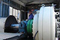
A MacTaggart Scott 100 series model HMB50 was selected — a multi-stroke, constant torque, radial-piston design with an integral brake. Internal motor leakage of a standard HMB50 motor operating at 4500 psi and 70° F is approximately 2 gpm, far exceeding the theoretical flow of 0.46 gpm required to achieve 0.035 rpm. This LSHT motor has pistons fitted with seals. Thus, the major source of leakage is a result of the valve plate used to port oil to the cylinders in the rotor. Oil leaks from high-pressure ports to low-pressure ports of the face valve, a condition referred to as cross-port leakage. Oil also leaks from both low- and high-pressure ports to the motor case. Modification to the motor’s internal valving was made to substantially reduce internal motor leakage.The motor was to be mounted with its shaft horizontal, and due to leakage, internal pistons in the upper motor segment would have the tendency to retract when the power was off. The addition of piston-return springs eliminated this problem. A self-priming capability allows for a simplistic manual emergency gate closing mode during loss of power or system failure.
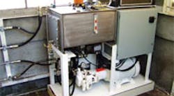
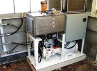
Because of the effects of slow speed and internal leakage, the flow rates into and out of the low-pressure port vary significantly from those of the high-pressure port. This was the basis for selecting an asymmetric control circuit. Further, to ensure a minimum volume of oil under pressure and maximum system stiffness, all control valving was manifold-mounted directly to the motor inlet and outlet ports. The hydraulic supply was provided from a separate HPU with a stroke-limited pressure-compensated pump set for 4 gpm and 4400 psi.
Operating the dam
When the dam is being lowered, a PLC starts the pump to develop system pressure. Next, a pressure-reducing valve pressurizes the high pressure port to 2400 psi. This is the theoretical pressure associated with the gate load. When this pressure is sensed via a pressure transducer, the brake is pressurized to release. The weight of the gate is then carried by pre-compressed oil and no gate movement takes place.The flow out of the high-pressure port passes a relief valve set at 3700 psi and the additional pressure necessary to achieve this is the result of oil being metered into the low-pressure port. The gate lowers as a result of the flow across the relief valve. This valve is externally vented to drain. For safety, a flow control valve rated to 2.8 gpm limits the maximum lowering speed to slightly greater than 0.2 rpm. If the gate tends to overspeed, the reducing valve will automatically compensate.
The oil being metered into the low-pressure port — to drive the gate down — is controlled by a proportional control valve. Unlike a standard valve, where flow is a linear function of command voltage, flow is an exponential function of voltage, so lower flows are readily achievable with greater accuracy.
An encoder measures counts, which in this application are units of 0.08° When the gate is within two counts of 0.08° of commanded position, the commanded voltage goes to zero and the brake is vented to drain. The gate stops either at commanded position or one count past.
When the gate is being raised, again the pump starts, the oil is pressurized, and the brake is released. Poppet valves block oil from the lowering relief valve and pressurize the highpressure port to 4400 psi.
On the low-pressure side, poppet valves are energized to configure the flow control valve in the meter-out state. The 4400 psi being applied to the high pressure port exceeds that required to raise the gate, and the flowcontrol valve restricts flow to maintain the commanded speed.
When the gate is within one count of 0.08° of commanded position, the commanded voltage goes to zero and the brake is vented to drain. The gate stops at commanded position.
The point at which action is initiated to stop gate movement varies from raise to lower. This was gleaned during initial startup, and it appears to be an effect of gravity.
Fine-tuning
The determining of command voltage to the proportional flow control valve is a two-step process continuously being performed within the PLC. The first step is to calculate the required flow through the valve. This flow is the theoretic flow required for the speed, plus the flow required to compensate for leakage. The theoretical flow is easily calculated. The net leakage from the low pressure port is low pressure case leakage minus cross-port leakage from high pressure.Each hydraulic motor has unique leakage characteristics and, using observations of operating at various speeds, pressures and temperatures, it was possible to create simultaneous equations and establish the variables for mathematical models.
The solutions were then incorporated into the control programs for each gate. The predominate leakage was cross-port, and leakage was into the low-pressure port. The result of this motor characteristic was that, without compensation, the speed raising was slower than commanded and faster for lowering. With compensation, this variant was reduced to a few thousandths of an rpm.
The installation and commissioning of the new hoist mechanisms for the gates was completed in 2005 and has proven to be a success. Multi-stroke LSHT motors capable of developing extremely high torque are compact and lightweight. The Leaburg Dam project required high torques at an extremely low speed and, hence, low power — an ideal application for multi-stroke, radial-piston LSHT motors. When combined with innovative computer- based control, the result was a reliable and economic solution to a challenging application.
For more information, email the author at joseph_urciuoli@ mactag.com.


