Hydraulicspneumatics Com Sites Hydraulicspneumatics com Files Uploads Custom Inline Archive Www hydraulicspneumatics com Content Site200 Articles 11 01 2008 83012 Versatilev 00000055108

Versatile Vane Motor Produces Virtually Constant Torque

Nov. 13, 2008
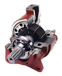
With its patented vane-crossing-vane design, this hydraulic motor provides low-speed, high-torque and high-speed, high-torque power from the same bi-rotational power converter. Working vanes in the rotor and sealing vanes in the stator are ...
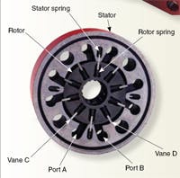
With its patented vane-crossing-vane design, this hydraulic motor provides low-speed, high-torque and high-speed, high-torque power from the same bi-rotational power converter. Working vanes in the rotor and sealing vanes in the stator are both hydraulically and spring loaded. When differential pressure acts on the rotor vanes, they exert rotational force on the rotor. Pressurized oil entering the A port pushes the rotor vane and rotor clockwise. While each rotor vane is finishing its work cycle in a cavity, another rotor vane starts its work cycle in that same cavity. Thus, multiple rotor vanes are working at any given time.

For example, as the vane marked C is in the middle of its work cycle (moving outward), the vane marked D is near the end of its work cycle (moving inward). Each rotor vane works once per cavity per revolution, so a four-cavity, 10-rotor vane motor would have 40 power strokes per revolution. The result: nearly constant vane extension — therefore, the output approaches constant torque, regardless of radial location.

The motor’s torque curves are virtually flat — with starting and stall torque equal to 90 to 94% of theoretical. Operation is smooth from less than 10 rpm to 2000 rpm and higher. As the rotor vanes approach the stator vanes, radii machined on the crossing edges at both vanes’ tips come into contact, allowing each vane to slide past the other.

Both rotor and stator vanes see the same pressure, but the wider rotor vane, having greater hydraulic and spring force, pushes the thinner stator vane back into its slot. (Because the rotor vane is wider than the stator vane slot, it cannot enter the stator vane slot.) The stator vanes function as highpressure to low-pressure seals between inlet and outlet ports, so more working cavities can be incorporated in less area. This improves both mechanical and volumetric efficiencies from a smaller and lighter envelope for a given displacement.

Specification summary

Four series (15, 37, 57, and 125) cover range of 21 displacements from 5 to 250 in.3/rev that produce continuous torque from 183 to 13,714 lb-ft. Pressure ratings for all standard models: 3000 psi continuous; 3500 psi intermittent. (High-performance models: 4500 psi continuous; 5000 psi intermittent.) Speed range: 2000 rpm continuous (smallest model) to 300 rpm continuous (largest model).

Make contact: Rineer Hydraulics, Inc.San Antonio, TX 78216Phone: 210/341-6333 www.rineer.com
About the Author

Richard Schneider | Contributing Editor

Contributing Editor, has been affiliated with Hydraulics & Pneumatics for more than 30 years and served as chief editor from 1987 through 2000. He received a BSME from Cornell University and also completed additional courses at the Milwaukee School of Engineering. His diverse background in industry includes ten years with a fluid power distributor and a variety of other professional positions. He has also been active with the National Fluid Power Association and Fluid Power Society.

Continue Reading

Motor leakage variations

Oct. 18, 2006
affect low-speed performance

The Impacts of Electrification on Fluid Power Systems

May 15, 2023
Electrification presents challenges as well as opportunities to re-evaluate and improve upon the design of hydraulics and pneumatics.

Sponsored Recommendations

7 Key Considerations for Selecting a Medical Pump

Feb. 6, 2024
Newcomers to medical device design may think pressure and flow rate are sufficient parameters whenselecting a pump. While this may be true in some industrial applications, medical...

How Variable Volume Pumps Work

Feb. 6, 2024
Variable volume pumps, also known as precision dispense pumps, are a positive displacement pump that operates by retracting a piston to aspirate a fluid and then extending the...

What is a Check Valve and How Does it Work?

Feb. 6, 2024
Acheck valve, a non-return or one-way valve, is a mechanical device that allows a gas or liquid to flow freely in one direction while preventing reverse flow in the opposite ...

The Difference Between Calibrated Orifices and Holes

Feb. 6, 2024
Engineers tasked with managing fluid flow talk about both holes and calibrated orifices, but they are two distinct entities. A hole can be any opening, but a calibrated orifice...