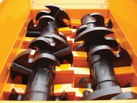
The ultimate goal for a shredding system is to reduce the source material — appliances, tires, concrete, etc. — to smaller particles for recycling. To transmit the low-speed, high-torque power needed for these heavy-duty shredders, a gearbox could be used to reduce speed from an electric motor while multiplying torque. However, hydraulics technology is a more practical solution both for systems driven through gearboxes and those that utilize low-speed, high-torque motors in direct-drive systems.
To ensure reliable delivery of hydraulic power, pumps are generally used for the drive application for the cutter shafts where a series of rotating cutters pulls debris from a hopper through small openings to shear and reduce its bulk. These pumps have a maximum continuous operating pressure of 5000 psi (344 bar) and a maximum theoretical flow of 238 gpm at 1800 rpm. In typical radial-piston designs, the pump may feed two pairs of hydraulic motors, with each mounted to either end of the cutter shafts.
Violent events
When it comes to the hydrostatic transmission design, shaft speed and operating torque are only the beginning. In reality, shredding produces a considerable amount of shock in the system. Envision driving your car at 100 mph, slamming on the brakes, then immediately going 100 mph in reverse. That’s what happens in shredding when the cutters jam — they reverse direction instantly, an extremely violent event! Furthermore, because the cutters can shear in both directions, it can take from one to ten revolutions of the cutter shaft to create a “violent event” prior to the reversal cycle.
Controlling when the cutter shafts reverse — and how long the reverse or forward cycle lasts — is programmable on some machines (within limits designed into the program). These programmable values can help to evenly distribute the loads, potentially extending shredder and hydrostatic transmission life, as well as the time between maintenance cycles.
Violent events can cause instant pressure spikes from 700 to 5000 psi (48 to 344 bar) within 100 msec. At the same time, the hydraulic hoses going to the pump from the motor can swell up, acting like a hydraulic accumulator. This swelling action can be detrimental if the replenishing system cannot make up for the instant loss of oil — as much as 100 gpm for the 100 msec. The total volume lost is rather small, but the instantaneous loss is substantial.
Because of their quick response, bladder type accumulators often are added to the system to aid replenishing, depending on hose length. You must take this accumulator effect into account for all types of hydrostatic transmissions during the initial design phase. Shorter hose lengths are best, but not always possible. A 1-gal accumulator is typical in applications with long hose runs. To accurately determine flow loss due to expansion from pressure, check with the hose manufacturer for bulk modulus values for different types of hose.
Because of the repetitive violent pressure spikes, the type of fluid used is also important. Whether petroleum base, or synthetic, fluids with a ZDDP (zinc dialkyldithiophosphate) anti-wear package are far superior to those with friction modifiers. Plus, it is good practice to check the fluid on a set schedule in conjunction with independent lab analysis to plot trends in contamination amount, type, and water content. Make sure the fluid maintains the additive package and viscosity. Pump and motor manufacturers can recommend parameters for maximum efficiency and performance.
Dealing with pressure spikes
Every pump manufacturer has a unique approach for rugged, severe-duty shredding applications. The key is to understand how the pressure spike will be accounted for — either across a relief valve, or through a valve block, as with Parker’s Gold Cup pump. If not accounted for with the proper equipment, the hydraulic system could be vulnerable to pressure spikes exceeding 9000 psi (620 bar). Many designers attack this issue by designing crossover relief valves into the circuit.
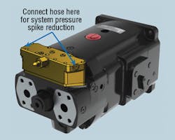
With the Gold Cup pump, a length of hose is placed on the valve block pressure port near the compensator poppet to act like an accumulator. This approach is less cost expensive than adding a crossover relief valve. However, a pressure spike of 700 to 5000 psi (48 to 344 bar) over 100 msec is a bit too fast for a pump’s compensator to handle and control.
Instead, the rapid increase in pressure swells the hose connected to the valve block. This initiates flow in the valve block that damps the spike. So instead of occurring over 100 msec, the spike is extended to 200 msec. This delay allows the pump’s compensator to react by destroking the pump before fluid pressure reaches 5000 psi. Cutting off the pressure spike (a feature unique to the Gold Cup pump) not only saves energy, but more importantly, it increases machine life by eliminating repeated fatigue loading on the system components.
Important HST info
Whether you’re designing hydrostatic drives for shredders, off-highway equipment, or whatever, it is critical to have open communication between your design team and the hydraulic pump and motor supplier. Topics that should be discussed include:
• system cooling capacity,
• pump efficiency for a given duty cycle,
• optimum efficiency parameters for the pump and motor,
• flow and pressure curves for the shuttle valve,
• the pump’s life expectancy and maintenance schedule,
• speed of the compensator,
• ability to manually set the compensator and replenishing,
• how the shuttle valve will be incorporated (mounted to the pump or remote mounted),
• the pump’s response time going on-stroke and off-stroke,
• the fluid type and analysis schedule for maximum life and performance,
• other non-catalog options available to improve performance, and
• control options for either flow response time or flow accuracy or both.
Know the fundamentals
Many common problems stem from users not reading the instruction manual, so they do not have a full understanding of the system. For example, a user set the accumulator charge pressure too high. As a result, pressurized fluid could not flow into the accumulator, so it was as if there was no accumulator in the system. This caused the pump to cavitate during fast response pressure cycles.
In system operation, it is very important to:
• maintain the proper pressure in the accumulators,
• change filters at recommended intervals,
• take fluid samples and perform oil analysis at regular intervals and plot trends,
• replace the reservoir filter breather regularly because a great amount of airborne dirt can be generated from shredding, and
• ensure that alarms, sensors, and overall operation are within manufacturer’s required recommendations.
Lowering the cost over time
Many pump designs for HSTs require a variety of add-on items. These may include external servo and replenishing pumps, replenishing check valves, relief valves, hot oil shuttle valves, and manifolds. Add-ons, of course, add to the cost of your pump. The Gold Cup pump incorporates these features in a compact, self-contained envelope that yields a more efficient and cost-effective system for long-term use.
Additionally, designers often provide added cooling flow to the pump case. However, by closely controlling temperatures, the Gold Cup pump improves efficiency by 1% to 2% by reducing the viscous drag.
When all the costs for procurement, installation, warranty and operation are considered, the greater savings benefit becomes obvious. Simply sharing technical information with the pump and motor manufacturer regarding the pump’s capabilities and long-term life potential can lower the total system cost by as much as 25% over the life of the unit.
Boost unit simplifies HST build
The BLA boost unit from Parker Hannifin’s Pump Div., Marysville, Ohio, simplifies the building of closed or semi-closed hydrostatic transmissions (HSTs) by replacing the conventional charge pump and corresponding valves in many applications including fan, propeller, generator, and pump drives. This can simplify the design and reduce the total cost of a hydrostatic transmission.
In a closed-circuit HST, a charge pump is typically included with the main pump to provide make-up fluid to replace pump and motor volumetric losses. The charge pump also maintains pump inlet pressure to avoid cavitation.
Parker’s BLA boost unit replaces the charge pump in many applications where the following conditions are met:
• maximum-to-minimum pump flow ratio does not exceed 2:1,
• system pressure changes gradually (no frequent or pronounced pressure peaks), and
• the line length between the pump and BLA boost unit is relatively short.
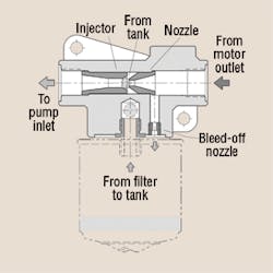
When fluid flows from the motor outlet through the BLA boost unit to the pump inlet (see drawing), the increased fluid velocity between the boost unit nozzle and injector creates a low-pressure zone, causing additional fluid to be drawn from the tank into the main circuit. Also, because pressure increases after the injector, the pump can be operated at speeds higher than the self-priming speed. Thus, boost pressure increases with flow.
Meanwhile, an additional bleed-off nozzle diverts approximately 10% of the main flow through a cartridge filter before the fluid is directed to the tank.
Parker offers two BLA boost unit models: the BLA 4 is available in four sizes with a maximum recommended flow of 10, 16, 26 and 42 gpm; the BLA 6 is available in 66, 92 and 105 gpm sizes. Both are constructed without moving/wearing parts and can be installed either directly to the oil reservoir or connected separately with piping or hoses. In both instances, the boost unit must be installed well below the lowest oil level in the reservoir to function properly.
For more information about the BLA boost units, call (937) 644.3915, email [email protected], or visit www.phpump.com.
For more information on the Gold Cup pump, call the author at (937) 644.3915, email [email protected], or click here.


