Hydraulicspneumatics 649 0402a

Specialty brake valves enhance mobile equipment

April 1, 2002
Because of the size of much of today's mobile equipment, hydraulic service brakes are a necessity. Engineers at MICO, Inc. add value to the brake components they design by ...

Because of the size of much of today's mobile equipment, hydraulic service brakes are a necessity. Engineers at MICO Inc., North Mankato, Minn., add value to the brake components they design by arranging for them to interface and interact with other systems on the equipment.

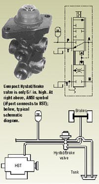
MICO's Hystat/Brake valve was developed to perform two consecutive functions on mobile equipment driven by hydrostatic transmissions: first to destroke the HST, and then to apply the vehicle service brakes. (Some equipment operators describe this logical combination of functions as inching.) Obviously, less braking effort is needed when the transmission is not driving.

Depending on the equipment design, the brake system may have a dedicated pump or it may be tapped into the main hydraulic system. Typically, an accumulator and charge valve ensure that pressure is available to operate the brakes. Inside the Hystat/Brake housing, two spools are mechanically linked to stroke simultaneously. When the operator depresses the brake pedal, the 2-position proportional spool connected to the HST swashplate control modulates that line to tank, and the pump de-strokes. With the HST in neutral, a pilot system between the spools allows the 3-position proportional spool to move independently - to apply the brakes and slow the vehicle. When the brake pedal lets the valve destroke, the brakes release, and the HST re-engages.

The compact Hystat/Brake valves are fully activated by 310 lb of push-rod force. They produce a maximum brake pressure between 500 and 600 psi. (Higher pressures are available in some optional models). Note that these valves can only be used with mineral-based hydraulic oils.

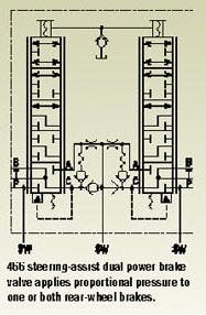
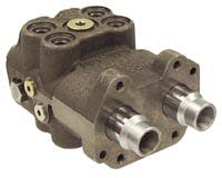
Another MICO product, the patented 466 steering-assist dual power brake valve, is aimed at equipment fitted with individual brake pedals for each rear wheel. This valve works in conjunction with the machine's steering system. When only one pedal is applied, the valve provides single-wheel power braking to assist the steering. With both pedals applied, it provides full-power braking - giving equal, balanced brake pressures. And when augmented by a properly sized accumulator, it provides emergency braking if the machine loses power.

An arrangement of check valves and orifices between the valve spools ensures that pressure on both brakes will be balanced, even if the operator does not depress both pedals an equal distance. This part of the circuit also prevents loss of fluid if there is a rupture in the brake system. Other benefits include smooth modulation at low pressures, and a pedal feel that accurately represents brake pressure.

The compact, integrated design of the 466 allows it to be adapted into a variety of hydraulic systems and many dual-pedal systems. With additional components, the valve can be used in open-center, closed-center, and load-sensing hydraulic systems on the vehicle, as well as dual-axle br
aking systems. The versatile mounting configuration allows the brake and pressure ports to be facing up or down, while the tank port can face in either direction. The housing includes a brake-light switch port (to monitor individual or balanced brake pressures), and auxiliary left and right side accumulator pressure-switch ports.

Note that both of the described valves are application specific — so they must be sized very carefully.

Click here to view a technical paper, Brought to a Stop, which describes braking system designs for off-highway vehicles.
Abstract: All mobile equipment needs brakes. Some, however, must also be able to "inch" into postion. Selection of the appropriate type of braking and inching configuration is often determined by the machine class and size.

Call MICO Inc., at (507) 625-6426 or visit www.mico.com.
About the Author

Richard Schneider | Contributing Editor

Contributing Editor, has been affiliated with Hydraulics & Pneumatics for more than 30 years and served as chief editor from 1987 through 2000. He received a BSME from Cornell University and also completed additional courses at the Milwaukee School of Engineering. His diverse background in industry includes ten years with a fluid power distributor and a variety of other professional positions. He has also been active with the National Fluid Power Association and Fluid Power Society.

Continue Reading

The Basics of Pressure Snubbers

May 29, 2020
Snubbers protect sensors and equipment in hydraulic equipment.

Pump placement predicates drive method

Jan. 16, 2014
Implementing a hydraulic pump drive—crucial to the layout of on- and off-highway equipment — can take one of several approaches.

Sponsored Recommendations

7 Key Considerations for Selecting a Medical Pump

Feb. 6, 2024
Newcomers to medical device design may think pressure and flow rate are sufficient parameters whenselecting a pump. While this may be true in some industrial applications, medical...

How Variable Volume Pumps Work

Feb. 6, 2024
Variable volume pumps, also known as precision dispense pumps, are a positive displacement pump that operates by retracting a piston to aspirate a fluid and then extending the...

What is a Check Valve and How Does it Work?

Feb. 6, 2024
Acheck valve, a non-return or one-way valve, is a mechanical device that allows a gas or liquid to flow freely in one direction while preventing reverse flow in the opposite ...

The Difference Between Calibrated Orifices and Holes

Feb. 6, 2024
Engineers tasked with managing fluid flow talk about both holes and calibrated orifices, but they are two distinct entities. A hole can be any opening, but a calibrated orifice...