Literature for servo and proportional valves contains a variety of terms and specifications that need to be understood for proper application. These specifications have been developed over the past half century or more and result from the confluence of
- the discriminating performance characteristics of the valve,
- the requirements of the most common applications, and
- the test procedures that tie the two together.
A complete treatise on the needs of the most common or typical applications can be a lifetime study all by itself. So rather than attempt a cursory overview of application technology, we will examine the test procedures in order to understand how the data was developed and analyzed. When the application is defined and studied, the valve specifications become more meaningful.
This file type includes high resolution graphics and schematics when applicable.
A battery of tests
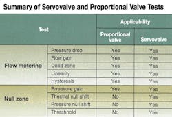
Typically, nine different tests are described, and their results are commonly reported in valve manufacturers' literature. For purposes of this discussion, a servovalve will be defined as one with less than 3% center overlap, and a proportional valve will be one that has more than 3% center overlap. The intent is to give significance to the technical literature and the specifications contained therein.
Valve lap refers to the amount by which the spool must move before there is any perceptible degree of opening. In a zero lapped valve, even a tiny amount of spool movement results in a commensurately small opening. This is what we'll consider to be a servovalve. On the other hand, those valves that require a substantial amount of spool movement in order to open will be considered proportional valves.
Complete derivations and additional explanations regarding the information and concepts that follow can be found in the Designers' Handbook for Electrohydraulic Servo and Proportional Systems.
A variety of tests has been devised for the evaluation of servo and proportional valves. Some are more meaningful than others, depending on whether they apply to a servovalve or proportional valve. For example, a proportional valve's relatively large overlap renders the critical null shift test meaningless. This is because the performance of the system is directly affected by the valve overlap. The larger the overlap, the less precise the controlled output in those null-seeking applications, such as positioning servomechanism.
The lay of the land
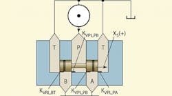
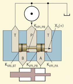
A typical four-way valve is shown in cut-away in Figure 1. Note that it is drawn with essentially zero overlap, and the method for shifting the valve, important though it may be, has not been shown for simplicity's sake.
The closed-center, continuously variable, four-way directional valve has four individual lands. All lands change simultaneously, with two going into an open state while the other two move into an over lapped state. Because each of the four lands is a physically different spot on the spool and body, each land is capable of its own degree of opening. This leads to the conclusion that each individual land has its own valve coefficient. However, although some valves are designed to have different land coefficients, most are symmetrical. That is, nominally, they have the very same degree of opening for a given spool shift, and, therefore, the very same valve coefficient.
The arrangement of lands is such that two of them communicate with the hydraulic supply (they contain pressurized fluid), which we'll call the powered lands. The other two are connected to and communicate with the return port or tank ports, and we'll call them the return lands. Thus, there are two powered lands and two return lands, each with its own valve coefficient.
When two lands are open the other two are closed, but closed within limits. Because they are spool valves, they never really shut off, because there is always some degree of spool bypass leakage. Sometimes we can ignore this spool leakage, other times we cannot.
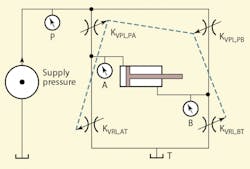
When the four-way valve is drawn in analytical schematic form, Figure 2, a bridge emerges, as do the identities of the P, T, A and B ports. Comparing the two figures shows how the orifices in Figure 2 correspond to lands in Figure 1. Each land is given its own subscript. For example, KVPL,PAis the valve coefficient of the powered land with P open to A.
Note that the lands are coordinated with each other such that when KVPL,PAopens, KVRL,BTalso opens, while the remaining two lands go into overlap, causing the cylinder to extend. Although we may refer to the overlapped lands as being shut off or closed, technically, they are not. However, when two lands are in overlap and two are substantially open, the amount of flow contributed by the overlapped lands is negligible and can be safely ignored.
Figure 3 shows the analytical schematic of the four-way valve when it has shifted: two lands are open and the opposite two are overlapped and can be ignored. So for analytical purposes, there are only two active lands. Therefore, an equation or set of equations can be derived that applies to either direction of shift, but the user must make the proper interpretations.
Matching valve to cylinder
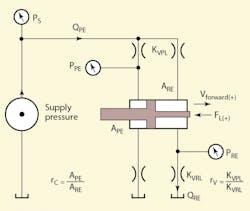
Redirecting our attention to the cylinder, imagine a vertical line running through the center of the piston. This line separates the piston's powered end from the return end. Thus, we have a piston with a powered end area, APE, because that area is communicating through the valve's powered land to the pump, while the return end area, ARE, communicates through the valve's return land to the reservoir (Figure 3). Therefore, the cylinder ratio, V, is the ratio of the powered end area to the return end area (APEARE,).
The powered and return end areas swap roles when the cylinder shifts from extend to retract, so the cylinder ratio changes as well. Because the lands change when going from extend to retract, we must define a valve ratio for each direction of motion.
Most valves, however, have identical valve ratios whether they are shifted to the left or to the right. But this need not be the case. Performance advantages can be gained when the valve ratio matches the area ratio of the cylinder.
How valves are tested
Valves normally are tested with the power and other connections set up for constant pressure drop across the valve. So the pressure drops across the four lands are measured under the condition of various control currents and various work port loading conditions. For servovalves, the flow rating pressure across the valve is 1,000 psi (7 MPa according to ISO 10770-1). For proportional valves, the standard flow rating pressure is 1 MPa (145 psi).
The test procedure for the above circuit, very briefly, is: Set the supply pressure to the flow rating value, open the load valve so that its pressure drop will be very small, then set the current to maximum in either direction. Adjust the load valve toward closure while recording all pressures and the output flow. when the load valve is closed, reduce the current by about 25%, then open the load valve while recording pressures and flow. Repeat this process for 50% and 25% of rated flow, and then repeat for current (or command voltage) of the opposite algebraic sign.
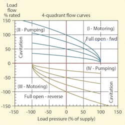
If the load valve is replaced by a pump, then it is possible to explore the valve characteristics with overrunning loads, which in extreme cases can result in cavitation of the powered end of the cylinder. The graphical results are shown approximately in Figure 4.
Figure 4 shows that the valve operates in all four quadrants of positive and negative forces and flows. That is the case in the application as well, and is normal, assuming that no over-running loads result in cavitation.
Details on this subject, including formula derivations, is available in Designer's Handbook for Electrohydraulic Servo and Proportional Systems, by Jack L. Johnson, P.E. o order, or for more information — including a detailed table of contents — visit the H&P Bookstore by clicking here.
This file type includes high resolution graphics and schematics when applicable.
