This file type includes high resolution graphics and schematics when applicable.
Most of the topics in this column have focused on industrial, or stationary applications. These machines usually feature some form of closedloop control, which requires continuous feedback of position, pressure or both. Mobile equipment, sometimes called off-highway equipment, uses a human operator to close the control loop. The operator’s eyes, ears, and touch act as sensors; the brain serves as the control; and arms, hands, legs, and feet operate the valves that control the hydraulic system.
Open-center valves are often used in mobile equipment because they accommodate fixed displacement pumps as the power source. The normal configuration is to combine several valves (spools, functions, or sections) into a sort of integrated circuit package called a valve stack. The two main configurations consist of tie-rod construction to hold the 4-way sections together, or, when economy of scale permits, the several sections are included in a single unblock or monoblock casting.
Manual control is the most common means of shifting spools in mobile equipment. These were also the very first proportional valves. The manual operation of the valves in the hands of a skilled operator becomes a sophisticated motion control system. Speed, flow, pressure, force, and position are all simultaneously controlled as if staged by a choreographer.
Several issues in the design of these hydraulic systems arise from subtleties and intricate interactions taking place in the circuit. The following bold points present some ways of looking at the circuits and their functions so that these subtleties can be understood and appreciated. They are the result of years of study in trying to gain a personal understanding.
Intricacies of mobile hydraulics
Fixed-displacement pumps are the preferred power source, so a flow division must take place, and the method of flow division depends on the specific valve. Sometimes the flow division is within the valve assembly, and sometimes not.
In most mobile applications, several valves are arranged into a single block, either bolted together with tie rods or contained within a single valve casting. This leads to great variety in design and construction details, many of which are proprietary.
A means must exist within the valve for building pressure as one or more valve spools are shifted, and the specific manner in which this takes place is a detailed function of the valve’s design.
Valves exhibit a load-induced, apparent dead zone. The dead zone, often confused with valve overlap, becomes greater as the load on an actuator increases.
Of course, there is the question of even calling the valve open center, because all four active ports in the center position normally are blocked, with the free-flow “open condition” being, in reality, a bypass function.
Should they even be called 4-way valves? Maybe 6-way is more appropriate, because, including the variable bypass function, there are actually six ports for each spool.
Perhaps the most complex issue is what happens when more than one function is shifted at a time. There are severe interactions among the multiple loads, the shifted spools, the varying bypass flow, and the pump output. Calculation and prediction are definitely possible, but some of the math can become almost oppressive.
Flow or pressure intensification, or both — and even regeneration — can occur when multiple functions are shifted.
Depending on the type of valve, shifting of an upstream function may result in the disabling of all downstream functions, but not so in other valve types.
Mobile equipment valves make ample use of the bypass flow path within the valve stack, and the coring in the castings can become complex and difficult to visualize. Therefore, it is not always easy to see how the flow paths are implemented with anything other than three-dimensional drawings.
Seemingly endless varieties in work port options add complexity to the schematic diagrams and can conceal the basic function of the 4-way valve itself unless you can separate options from function.
Many modern mobile equipment valve stacks are augmented with further variety in the integration of pressure compensation controls, often with the aim of controlling flow, or to reduce the interactions as a result of simultaneous shifting of more than one spool.
Add to the above issues that the standardized ISO symbology does not provide a complete picture of how the valve achieves proportionality, which can only be hinted by the convention of placing the “proportionality lines” alongside the 4-way spools, shown in Figures 1 and 2.
open-center stack valve circuits are used in mobile equipment: full series connection, partial series connection, and parallel connection. Each has its own peculiarities and interactions. Some of them will be covered in future editions of “Motion Control.”
Unloading compensator valves mimic the by-pass design in that they are capable of relieving fixed displacement pumps when the spools are all in neutral and give further question to the idea that they are even open center valves. Again, there are special circumstances in implementing these valves.
Unloading valve stacks all have some form of pressure sensing and piloting, which further adds to the mixture of possibilities in opencenter valves.
Because today’s equipment makes greater use of electronically actuated valves, electrohydraulic issues must be dealt with.
These observations are listed to summarize some of the issues at work with open-center, multi-function hydraulic valves with the intent of developing an orderly approach that helps in understanding them. Toward that end, there will be three different types of diagrams used to explain the valves:
• ISO schematic symbols
• combination pictorial cutaway and schematic diagrams, and
• Analytical schematics.
We’ll begin with the ISO schematic symbols, and cover the balance next month.
ISO schematic symbology
ISO schematic symbology is good at showing the logic of directional control valves; however, it falls short when it comes to showing proportionality — that is, the process of gradually opening the valve to control actuator motion. This is true not only of electrically controlled proportional valves, but also of manually controlled valves, which are common in mobile machines.
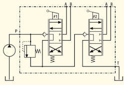
The ISO symbology allows conveying the concept of proportionality through the use of the parallel lines that are just outside the spool outline. Figure 1 shows a 2-function valve stack that is manually operated, powered by a fixed-displacement pump and has two 4-way directional control spools. This diagram is called the simplified, full series connected, opencenter, directional control valve stack schematic. It will be referred to here as the simplified, full series valve.
When the spools are centered, Figure 1 shows how the flow from the pump makes its way through the first check valve, into the center section of spool #1, out the exhaust port of section #1, and then to the second check valve and through the center block of spool #2. It is essential to note that all the flow reaching the second function must pass through the first section. The two 4-way sections are said to be in series because they both carry the same flow.
The next essential point is to realize why it is called a full series connection, rather than partial series connection. As spool #1 shifts to a partially open condition, some of the flow that enters its inlet is sent to spool #2, directly through the spool #1 center. Meanwhile, the balance of the flow moves through the open land of spool #1 to the load (actuator). For sake of discussion, fluid flows out work port A and returns via work port B. That return flow recombines with the center flow, so spool #2 receives all the flow that entered the first function — cylinder area differentials not withstanding.
This is difficult to explain in words because the ISO schematic symbology fails to clearly depict the proportioning, the internal flow dividing, and the recombining of the return flow. These vital functions of the valve are only implicit and left to the mental wizardry of the viewer.
Bypass flow path
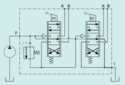
Recognizing the shortcomings of the symbology, inventive engineers devised a somewhat modified way of showing the full series valve stack. This method also uses conventional ISO symbols, but it also includes a more complete picture of valve construction. It shows the bypass path that unloads the pump when the valve is centered. The schematic is shown in Figure 2.
This schematic configuration clearly indicates that there is a separate path within the valve that routes fluid back to tank under low pressure when the spool is centered. This feature is found in most modern valves, so this representation helps describe a bit more about the physical construction of the valve.
However helpful this schematic representation may be in providing useful construction detail, it still does not convey even the slightest insight into proportionality. Another kind of drawing is needed, namely, a combination cutaway-schematic line drawing. The valve cutaway should show the spool and valve body parts in realistic relationship to one another, and the schematic line drawing would indicate how the multiple valve sections within the stack are interconnected. This is where the discussion will pick up next month.
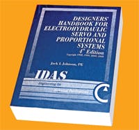
Introducing the fourth edition of popular handbook
The newly published fourth edition of the Designers’ Handbook for Electrohydraulic Servo and Proportional Systems is an expansion and improvement upon the popular third edition that some referred to as the “bible of electrohydraulic technology.”
The fourth edition includes subject matter that has been requested by readers demanding more insight into this growing technology. Readers requested more methodologies for analyzing hydraulic circuits. The response is a whole new Chapter One — Physics of Hydraulic Fluid Power. Nowhere else can you find the wealth of methods and example problems for handling the twists and bends of plumbing and manifolds and the like, allowing better design-time control over pressure losses and the design of more efficient hydraulic circuits.
Three chapters were added to deal with methodologies and example problem solutions for mechanical loads. These three chapters show you how to reduce loads to their four essential elements, reconcile them through gears, pulleys, or whatever, and then shows how to solve problems with triangulated loading, cylinders, and their linkages, which are common in hydraulic applications, especially mobile equipment. More methods were requested for control systems and modeling, so a chapter was added on how to make a completely linear, yet utilitarian, analysis of a motion control servo system having an unequal area cylinder. That chapter is followed by one that shows how to include the dynamic limitations (frequency response) of the control valve in a hydraulic system. The result is a unique approach to an old problem, yet solutions are eminently practical. No other publication shows you this kind of analytical power. For the first time, a new chapter has been included on the optimal sizing of hydraulic motor circuits.
Finally, three new chapters have been added to teach you about the ever-increasing role of electronics in hydraulic control systems. There is a chapter on basics of electricity and electrical measurements; another is a veritable catalog of tutorial explanations of the common electronic devices needed in the modern electrohydraulic system, including all the popular transducers and signal conditioners. All of it is demystified for you.
Readers also wanted more on mobile equipment electronic systems, so that has been added in a special chapter. You will have answers to how batteries work their seeming magic (and what you need to do to help them), how vehicle charging systems work, and how joysticks work and interface with the rest of the electrical system.
In all, nearly 250 pages have been added, creating an indispensable reference of 784 pages. It is the musthave technical reference for anyone wanting to get on board the electrohydraulic technology juggernaut.
The book sells for $149.95, plus $5 shipping and handling from the H&P Bookstore. Visit www.HydraulicsPneumatics.com and click on the Bookstore button to order. Once at the Bookstore page, scroll down to the hyperlink to download a PDF order form. Fill out the form and fax it to the number indicated.
This file type includes high resolution graphics and schematics when applicable.


