By Jack L. Johnson, P. E.
The last several editions of “Motion Control” explored open-center valve design concepts and showed that the term open center is considered as a misnomer by some observers. This is because the 4-way lands are often all closed, with pump pressure relieved only because of a separate bypass path, whereas the more conventional interpretation has all the 4-way lands open. In spite of the conventional wisdom and interpretation, the valves are useful because shifting of the spool not only opens the 4-way lands, but also closes the bypass path. This allows pressure to build up to meet load requirements and relieves pump pressure with all spools centered.
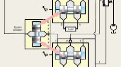
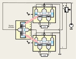
Are there other means for performing the bypass and center relieving function? The answer is, yes, and Figure 1 introduces the concept. Here, the valve is equipped with a separate unloader spool that bypasses the pump flow when the 4-way spools are centered. The red double arrows in the illustration imply that the bypass spool, labeled Bypass unloader, is linked, or synchronized with the 4-way lands. There are three possible ways to achieve this synchronization:
• mechanically, with cams and followers, thus mimicking the conventional designs discussed previously,
• hydraulically, using piloting methods, or
• electronically with proportional solenoids.
Synchronizing operation
Of the three methods, the hydraulic piloting method is the most common. However, as electrohydraulics gains acceptance in mobile equipment, the electronic method will become increasingly popular. Electronic methods also offer the greatest possible flexibility and tailoring of valve operational characteristics. However, they will not be dealt with here, because the technology has yet to emerge definitively and with full industry acceptance.
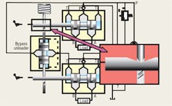
Figure 2 shows a possible mechanical linkage system that uses a series of cams connected to the 4-way spools so that as a 4-way spool shifts, the bypass land is likewise shifted. The arrangement of the cams and followers gives control of the bypass spool to the 4-way spool with the greatest amount of shift, while spools with lesser shifts are ignored. Changes in cam design can modify the amount of shift required of each spool to control the bypass flow. The configuration in Figure 2 is the parallel hydraulic connection. Its performance characteristics — including the apparent dead zone caused by load pressure — are essentially the same as the more conventional design discussed in previous editions of “Motion Control.”
Sensing load pressure
The bypass unloader is drawn off to the side in Figure 2 to conveniently illustrate the mechanical linkage. In fact, the unloader spool is normally located within the inlet section of the valve stack. It needn’t be.
At least one manufacturer offers a fixed-displacement gear pump with the unloader spool integrated with the pump. The bypass spool is not operated mechanically; rather, pilot pressure is used. However, bypass spool control can also be accomplished electronically with pump unloading. In addition, the pump-mounted unloader spool requires a load-pressure sense or pilot line connected from the 4-way valve stack to the pump, just as with load-sense pumps. In fact, the external characteristics mimic a loadsense pump, but without the attendant higher efficiency.
The conventional bypass valve design (with bypass lands at each spool), has the disadvantage of requiring the bypass flow to go through all the lands on its way to the tank. This either requires relatively large bypass lands or results in a higher pressure loss in neutral. Also, the individual bypass lands interact during partial, simultaneous spool shifts. This makes prediction of pressures and flows a complex mathematical process normally requiring a computer to solve. Such processes are beyond the scope of this discussion.
The only significant advantage the design concept of Figure 2 has over more conventional open-center stack valve designs is the potential for less neutral pressure loss. However, higher manufacturing costs offset this advantage, so the method is not commercially viable.
With the unloader designs, only one bypass land services all spools in the stack. It can be sized to provide the necessary neutral pressure, commensurate with the pump output flow at maximum pump speed. Bypass flow still must thread its way through oftentimes intricate pathways within manifolds and subplates. However, those are passive paths, not active as in the spool type bypass designs. Greater opportunity exists to lessen neutral pressure drops with the unloader designs. Also, there are more ways in which to link the unloader action to the 4-way spool shift.
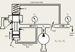
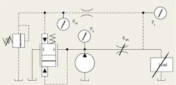
Figure 3 is a simplified diagram and schematic consisting of the unloader spool in cutaway with the 4-way valve characterized only as a simple variable orifice, KVPL. A sense line connects the load to the spring cavity on one side of the unloader spool. Meanwhile, another sense line connects to the opposite side of the unloader spool. Other spools in the stack and other lands in the valve are omitted for simplicity in illustrating the operating principle behind unloading valve operation.
Note that the unloader spool’s bias spring, labeled KS, biases the unloader spool in the closed position. That is, the unloader function is normally closed. The unloader spool will not open until the pressure through the pump sense line exceeds the load sense pressure by the amount of bias spring plus flow forces acting on the unloader spool.
Valve designers select the spring so that the differential pressure required for cracking the unloader spool (just starting to open) requires from about 50 psi to as much as 250 psi. The higher pressure provides for better control, but it also results in higher unloading pressure and, thus, lower efficiency of the valve system.
Unloader valve issues
A few issues with unloader-type valves are worth discussing. The first is that the unloader spool processes two pressure signals in a way that attempts to maintain a constant pressure across the powered land, KVPL. In so doing, the unloader spool regulates the flow to the load, at least in this simplified scenario.
This raises the second point: As the load pressure changes, the powered land’s pressure drop is maintained, and flow tends to remain at a value determined by the degree of shift of the 4-way spool — not by the load or even pump pressure variation. This kind of control is easy for even the novice operator to use because of the nearly independent nature of the flow control. A human operator need not compensate for load pressure changes; the unloader does it automatically, somewhat.
However, this is a somewhat idealized description. Practical aspects bring us to a third point: Although many designers of these valves insist that the pressure drop across the powered land remains constant, indeed, it does not. When tested at a variety of loads and KVPL settings (differing amounts of 4-way spool shift), the differential pressure will vary between the cracking value up to as much as twice that amount. Nonetheless, the differential pressure drop will not, in this simple, single function scenario, vary by any large amount from the design cracking value.
This brings up a fourth point: Because the differential pressure drop is maintained at a relatively low level at all operating conditions, the flow forces acting on the 4-way spool are small, making it easier to shift and maintain than in other designs of previous discussions. This results in less operator fatigue, and when electrically activated with proportional solenoids, it also means that the solenoid current determines the flow, not the load and supply pressure. This contributes to operator friendliness of these valves.
A fifth point is that the flow regulation is imperfect. It can vary depending on supply pressure and load pressure, but not nearly as much as without the unloader function. Also, flow forces act to close the unloader valve and, in essence, make the bias spring seem stiffer than it is. The result is overcompensation; that is, as load pressure approaches the pressure rating of the valve, the load flow decreases.
This conclusion has been witnessed through countless tests and confirmed through math modeling and simulation studies. None of this is meant to denigrate these valves. Rather, the intent is merely to explain certain idiosyncrasies in the hopes that the valves are understood and more appropriately applied.
Figure 4 is included simply to illustrate that there are conventional ISO symbols for the unloader compensator. It should be compared to Figure 3.
Handbook serves electrohydraulic system designers
The fourth edition of the Designers’ Handbook for Electrohydraulic Servo and Proportional Systems contains even more useful information than its predecessor, the highly successful third edition, which has become the Bible for electrohydraulics technology.
Now you can learn even more about electrohydraulic systems and their design, including:
• how to calculate and control pressure losses in plumbing, subplates, and manifolds,
• how to analyze and control a variety of mechanical loads, including conveyors and belts and triangulated loads,
• valve dynamic properties and how to include them in your system,
• electronics, especially transducers and signal conditioning, and • mobile equipment electrical systems, including batteries and charging systems.
There is no limit as to how electrohydraulics is going to revolutionize our industry, so order your copy to secure your career in this dynamic technology. And if certification in electrohydralics is your goal, the fourth edition of the Designers’ Handbook is essential to your preparation. Don’t risk being left behind in a world where the only constant is rapid change.
To order, visit our website at www.hydraulicspneumatics.com, and click on the Bookstore button. Print the PDF order form, fill it out, and mail, fax, or e-mail it to us.
