By Jack L. Johnson, P. E.
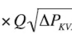
Before concluding the discussion from last month, it will be helpful to review the equation for flow force because it begins to exert its effects on the valve performance any time pressure exceeds zero. Here is one of the general forms of the flow force:
Where fQ is flow force acting on the compensator spool in a direction to close the valve, lb,
KQ is flow force coefficient, (lb/√psi)(in.3/sec)
Q is flow through the compensator spool metering land, in.3/sec,
ΔPKVX is differential pressure drop across the compensator spool, psid, and ΘQ is the angle of the flow as it passes through the compensator spool’s metering land, °.
The important observation to be made from the equation is that the flow force is affected by both the flow through the valve and the differential pressure drop across it, along with the flow discharge angle. After compensator spool lift-off, both flow and pressure increase until maximum flow is reached. Flow then stays constant, more or less. However, the pressure continues to go up, because the supply pressure is being increased. Thus, the flow force continues to increase and acts in a direction to close the compensator spool window openings. The result is a flow force that works against the bias spring so that the flow actually decreases, even though the pressure is increasing. Therefore, the flow force causes the flow to decrease for large 4-way valve openings. Later, we’ll look at the improbable result of having no flow forces (an advantage of the math model), which reveals the effects dramatically.
Three alternatives
In contrast to the flow dropoff at the largest 4-way setting, 11.5 holes, the lowest 4-way settings provide very good flow regulation at higher pressures. So what needs to be done to get the curves for large 4-way openings to be flat like the small 4-way openings? Three things can be done, but they can be costly, and at times, prohibitively so.
The first possible change is to make the spring stiffer. Because flow force acts to close the valve, and the spring acts to keep it open, a stiffer spring will keep the spool windows open at high pressures, and, thus, raise the flow at the highest pressures. This ploy has a down side, however.
The stiffer spring will likely require larger diameter spring wire, resulting in a longer solid height. This will necessitate a longer spring cavity, and, of course, a longer overall cartridge length. This may or may not be acceptable. This alternative also results in a higher maximum output flow, all other things remaining equal. Because of the stiffer spring, the spool windows remain open until a higher differential pressure is reached, and, thus, higher peak flow. At the same time, the pressure at which the maximum flow occurs tends to increase.
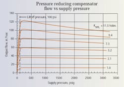
The second alternative is to limit the use of the cartridge to control smaller 4-way valves. That is, if the full opening of the accompanying 4-way valve is, say, 5.2 holes, instead of 11.5 holes, flow regulation is much better, as shown in Figure 3. Valve designers do not like this option because they want to push as much flow through a given valve as possible.
The third, and most effective design change, is to increase the diameter of the compensator spool. The compensator spool, by virtue of its area and the design of the cartridge, is, at once, the variable orifice that regulates output flow and the differential pressure sensing element. When its diameter is increased, more force is developed for a given differential pressure (pressure drop across the 4-way powered land). This increased pressure force renders the flow force less significant, relatively speaking. The result is better flow regulation at the higher 4-way opening because the flow force is less significant.
The down side is at least two-fold. First, the compensator necessarily becomes bigger, and it will certainly be more expensive. Another issue is that as soon as designers discover that an even larger 4-way opening will result in more output flow, they are tempted to join the compensator with bigger 4-way valves, and the result is a commensurate deterioration in flow regulation. I know, I’ve been there.
Speed regulation
At the very least, users of these valves should provide a clear requirement to the valve designer as to the flow regulation needed in the application. For example, in Figure 3, the flow varies from a maximum of about 124 in.3/sec, then falls off to about 96 in.3/sec, producing a range of about 28 in.3/sec for the maximum 4-way opening. The midpoint output flow is about 110 in.3/sec, meaning that the valve manufacturer should specify that this valve and 4-way combination provides 110 ±14 in.3/sec. This calculates to about ±14% output flow regulation in the range of lift-off pressure (100 psi) to more than 3000 psi.
The speed of the output actuator will also vary by that percentage, internal leakage notwithstanding. But if the valve user specifies to the valve designer a very specific speed or flow regulation value, the best possible combination can be designed, built, and delivered. Valve designers who are not now using good math models of their compensator valves should be; they are powerful tools when investigating the myriad “what ifs” of valve design.
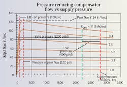
So far, this discussion has been limited to the condition that the load pressure is zero. This, of course, is not the case in the application. Figure 4 will now be used to give some insight into interpretation of the performance characteristics in the face of varying load pressures.
Figure 4 is a repeat of the performance characteristics shown in Figure 3, but with some added notations. The figure has red and green notations. Begin with the red notation, and observe that the application scenario has the supply pressure set to 2800 psi. A vertical red line appears at that pressure, and a green vertical line appears at 2200 psi. This corresponds to a load pressure of 600 psi (2800 – 2200).
System dynamics
Now imagine that the supply pressure is set to 2800 psig, say, with a pressure compensated pump, while the load pressure is zero. In Figure 4, the green line would lie directly on top of the red line. Then if the load pressure starts to increase, the green line will shift to the left. We can see, then, that for the given scenario, the supply pressure is 2800 psi, the load pressure is 600 psi, leaving 2200 psi to be absorbed by the compensator spool and 4-way valve.
What, then, are the consequences in the application if the 4-way valve is fully opened (the valve coefficient becomes 11.5 holes)? As the load pressure increases, the green line moves to the left, flow to the load increases, and output actuator speed increases as well. This is somewhat counterintuitive because we normally associate increased load pressure with a decrease in flow and speed. Not so with such valves. The degree to which this phenomenon occurs relates directly to the performance characteristics as displayed in Figures 3 and 4. We say that the valve “over-compensates” for pressure variations.
An alternate situation
In another scenario, instead of the supply pressure being set by a pressure compensated pump, suppose it is affected by the shifting of another function in the valve stack. That is, suppose we start with only one function shifted, and that load has a lowload pressure, say, about 200 psi. We’ll also stipulate that the supply pressure rises to only about 500 psi due to valve loss. Valve pressure drop, then, is the difference, equalling 300 psi. This means the output flow to the actuator will be about 120 or 124 in.3/sec, and its speed will reflect that flow.
Now, suppose the second function is shifted that has the higher pressure, and say it causes the supply to go to 2800 psi. Because of the shuttle valves that were discussed in a previous edition of “Motion Control,” the pump pressure rises to meet the highest load requirement. The compensator spool in the lower pressure function automatically closes off as it absorbs the excessive pressure and tries to regulate its output flow. However, because of the inherent drop off in flow, the output actuator slows down. It was going along at some speed before the second function was shifted.
When the second (higher pressure) spool was shifted, the first load slowed down. The intuitive conclusion is that we are “running out of pump,” or there is excessive internal leakage in the pump. However, increasing pump output flow will not correct this problem. It is caused by the over-compensation of the pressure- compensated flow control valve. A compensator is needed with better flow regulation characteristics. Load isolation is not perfect.
Summarizing flow regulation
What’s important is realizing that the load interactions with simultaneous valve shifting are a matter of degree. Many times, the only measure of output speed is the observation by the machine operator, whose speed perception skills may be less than perfect. In these cases, speed variation may not be all that important. But when physical measurements are made, or when a bucket must clear the side of a truck in a specified amount of time, function sluggishness can spell the difference between success and failure. The system designer should select a pressurecompensated flow control valve with better regulation.
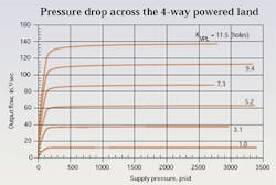
Figure 5 illustrates the pressure-flow characteristics of the circuit and control valve when no flow forces are present. Never mind that total elimination of flow force is physically impossible. In the world of mathematical modeling, such “what ifs” are entirely explorable. To generate the data for Figure 5, one input data item was changed to a value of 0.0. That’s all that is necessary to see the effects of having no flow force.
It is not arguable that the flow regulation is much better than the real valve. Inventive designers have altered the valve geometry to direct the flow path in such a way as to counteract the effects of flow force. However, to my knowledge, no one has been able to do that with the cartridge design because of the shape and size of the spool. It would also add significant cost to manufacture the valve parts.
Basic Electronics for Hydraulic Motion Control
This is where your basic electronic training starts. This book, unlike many others, is written specifically by a practitioner of the hydraulic art for engineers and technicians working in hydraulics, but it teaches you all you ever needed to know about electronics. Your personal understanding of hydraulics is your ticket to learning electronics with this book, which is filled with analogies to simplify the understanding of concepts.
Everything you wondered about and need is here: transducers, interfaces, signal conditioners, pulse width modulation, controllers, amplifiers, transistors, analog electronics, digital electronics, and much more. It is a must read and reference for anyone interested in certification in the exploding technology of electrohydraulics.
It uses your knowledge of fluid power to help you learn and understand electronics. Order your copy now and get the book that makes electronics fun and easy to learn.
Authored by Jack L. Johnson, P.E., edited by Hydraulics & Pneumatics, and published by Penton Media, the hard cover textbook (ISBN 0-932905-07-2) contains 438 pages and sells for $99.00, plus shipping and sales tax. To order, or for more information, visit our Bookstore and download the PDF order form.
