In the world of pneumatics, a major influence on the speed of a machine is the flow rate achieved by the directional control valve. The directional control valve acts like an on/off switch that supplies the compressed air to the point-of-use devices, such as a cylinder, gripper, or vacuum generator. The valve can either be on or off, with air flowing through the valve to either extend or retract a cylinder.
Valves come in varying sizes, and flow rate is often used to reference the valve and put it into some sort of perspective. Flow rate is typically measured in units of ft3/min (cfm) or lpm. More commonly, the flow rate of a valve is described by a dimensionless value known as CV, the flow coefficient.
Maximizing flow
Every component in a system through which air flows can serve as a restriction. A restriction will ultimately slow down motion. The challenge faced by designers of pneumatic systems is to minimize the number of restrictions introduced into the pneumatic circuit beyond the valve.
The valve is selected to route a set amount of air to allow the cylinder to operate at a specific rate. Because of this, each component of the pneumatic system should be selected so that it does not introduce additional restrictions that may reduce the cycle times of the cylinder. For example, fittings and tubing are common restrictions that can significantly reduce the air flow seen at the point of use.
Considerations on exhaust
The valve itself is an item that can inadvertently introduce a restriction. An example of this is when the exhaust ports of a valve are under-sized from the supply and working ports. Some valves may have 1⁄4-in. supply and working ports, but 1⁄8-in. exhaust ports. This restriction to the exhaust will slow down the total system throughput.
In a practical view, it is important to have a high flow rate through the valve to a cylinder, but if you cannot exhaust air at the same rate, this restriction slows down the machine's overall speed. This is something that is often neglected when selecting a valve.
Differing valve styles' effect
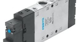
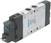
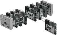
Flow path is also very closely tied to the CV you can achieve with a specific pneumatic valve. For example, with an in-line valve, Figure 1, you can typically achieve the highest CV because the air path has a minimal amount of bends, keeping pressure loss at a minimum. Although manifold mounting does have advantages for saving on installation costs (where it is practical to have a group of valves located together), there is often some drawback as to the flow rate you can achieve, in relation to an in-line valve of a similar physical size. Of the various manifold mounting options, the highest CV can be achieved with a valve incorporating a plate design. This is where the manifold is actually combined within the valve body or slice, Figure 2.
With a plug-in valve, all pneumatic and electrical connections to the valve are made via the sub-base. This makes it easy for maintenance to exchange a valve, as they would typically only need to remove two screws. No tubing or electrical connectors need to be touched. This makes it one of the most popular styles of valve manifolds. However, it has the biggest challenge achieving a high CV.
Because the air now makes many turns before exiting to the working port, it is possible that restrictions are introduced into the system. This is where good product design can be used to minimize losses in sub-bases to achieve high flow rates. Rounded corners instead of sharp edges, smooth transitions instead of abrupt changes, and sufficient area in the supply and exhaust channels are all important design factors that can be used to get the best possible results.
Sandwiching elements
An accessory commonly used with plug-in sub-base style valve manifolds is a sandwich style function plate. These sandwich plates can contain functions like flow controls or pressure regulation. The purpose of a flow control valve is to restrict the flow from the main valve, but when using a sandwich style pressure regulator, sometimes unexpected effects on the CV can be seen.
With a sandwich pressure regulator, there are internal flow path turns that have an effect on the flow, as well as the physical size constraints of the valve. Depending on the design of the sandwich regulator, it is possible to see a reduction in flow rate by 60% of the valve's flow capability. Sandwich regulators offer the advantage of saving energy by using only the pressure required for an application. As a result, there is less wear and tear on the actuators. However, the system designer must keep in mind the effect on flow and overall speed. There is no right or wrong solution; it is simply important for the designer to be aware that the use of a certain type of componen can affect the overall flow in a branch.
Maintenance
Poor maintenance of a system, such as having dirty/clogged mufflers, will affect system performance.
Just as undersized exhaust ports can lead to slower than expected machine cycle rate, so can clogged silencers. A clogged silencer that restricts exhaust flow has the same effect as an under-sized exhaust port. Proper maintenance of a pneumatic system will lead to better performance for a longer period of time.
Physical location
When a system designer is selecting a valve, he/she needs to take into account the location of the valve in relation to the actuator. Flow through a tube will naturally have some pressure loss, due to the length of the tube.
Of course, considerations such as size of the valve and available space, accessibility to the valve for installation/repair/exchange, and location based on protection (e.g., avoiding a washdown area) should be taken into account and will help determine the necessary valve size. However, using a smaller valve (smaller CV) closer to the actuator/end effector could provide a better overall performance than using a larger valve further away from the actuator/end effector.
The advantages of using smaller valves are: they typically are lower cost than larger valves, they have lower flow rates, they use less air to perform the same work saving energy costs, and they also would typically have lower leakage rates — again resulting in lower energy costs.
Contact the author, Frank Langro, at (631) 404-3213, or email him at [email protected]. For more information, visit www.festo.com.


