Traditional pneumatic directional valves use either a poppet, spool, or sliding plate operating principle. The most common design is the spool principle as it offers a good balance of reliability and durability vs. cost for many industrial automation applications.
One concept that is gaining popularity is the use of split spool or dual 3-way, 2-position valves (in one valve body) which are directional valves that give independent control over both spool valve outlet ports. This reduces cost, weight, and space with no loss in performance.
Split spool valves
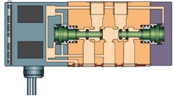
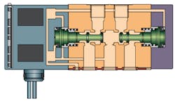
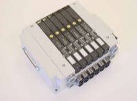
The traditional spool valve has one single spool. Whether the valve is a 2-position or 3-position configuration, it has one solid spool. The split spool valve has two shorter spools in the same axis that are completely independent of one another, Figures 1 and 2. The valve has the same number of ports with the same mechanical and electrical interfaces as any traditional single-spool configuration so it can be mixed and matched with them on the same manifold, Figure 3.
The dynamic sealing principle and geometry is the same as a traditional spool valve in the same series so the same performance in terms of flow and durability can be expected. The valve functions are termed as 3-way, 2-position normally closed (NC) or 3-way, 2-position normally open (NO). Split spool valves can be used to functionally replace 5-port, 3-position pressure-center and exhaust-center valves with no loss in performance.
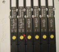
Split spool valves are available in sizes with flow rates up to 1.4 CV and higher. They are available with ISO 15407-1 and 2, as well as ISO 55991 and 2 standard interfaces. Valve manifold series that offer various sandwich pressure and flow control options are usually inherently compatible with split spool valves, so a user would not lose the advantages of these modular accessory devices. The manual override on a split spool valve will have five positions, so the user does not lose that functionality either, Figure 4.
When 4-way valves with ports plugged are used for 3way, 2-position NC control, all exhaust air typically goes through port 5. Split spool valves in the same applications would have the exhaust air divided between ports 3 and 5 which would typically result in lower exhaust backpressure. Lower exhaust backpressure means faster cycle time for actuators. In some cases, high backpressure can cause actuators controlled by manifolded valves to reverse motion or be unable to deliver enough force for the application requirements.
Mounting variations
Many applications in industrial pneumatics use valves individually mounted. From a purely pneumatics efficiency perspective, the ideal location for a directional valve is on the actuator itself which minimizes the volume of air in the conductor between the valve and the cylinder. Individual mounting of valves also gives the designer autonomy in selecting the size of the valve for the specific application which can also save costs.
In reality however, a typical automated machine has its pneumatic solenoid valves manifolded together. The main reasons for manifolding the valves are:
- Manifold valves lead to cleaner, more integrated control packages with just one or two supply and exhaust points for several valves.
- A valve manifold typically allows easier valve mounting and valve replacement than body ported valves.
- Solenoid valves are controlled from some type of electrical output module with individual wires to each valve or increasingly a serial link module integrated in the valve manifold itself.
In any case, the electrical outputs are close together on one device. In the case of the integrated serial link, manifolding has a large bearing on the cost of the valve manifold.
The example circuit that requires the highest flow often determines the valve size for all applications. For example, on a seven station valve manifold, if six applications require 0.3 CV, and one requires 1 CV, the odds are high that all applications will have the 1 CV valve. Valve series are available with transition plates between valve sizes, and some valve series even have different body sizes that can be stacked laterally without transition plates, but they are a minority.
Usually, two electrical addresses are allocated per manifold station. This is not a rule, but designers tend to use manifold bases with two electrical addresses to make the overall addressing more intuitive, easier to debug, and to maximize component commonality.
Valve options for manifolding
Traditionally, manifold systems for all 3-way valves have been commonly used for process control applications. For automated assembly applications with flow rates to 1.0 CV and higher, until recently the overwhelming majority of spool versions available had been confined to either 5-port, 2-position or 5-port, 3-position. A typical manifold valve series would consist of: 5-port, 2-way single solenoid return; 5-port, 2-position double solenoid; 5-port, 3-position supplied (pressure) center; 5-port, 3-position exhaust open center; and 5-port, 3-position blocked center.
Many large end users of pneumatic equipment have long recognized the advantages of allowing only components with ISO interchangeability in their plants. Many equipment manufacturers also ensure greater acceptance of their machines when they market them as designed with ISO interchangeable components. Until the past few years however, ISO standardization for valve manifolds offered severely limited choices when it came to compact pneumatic control.
Benefits of Split Spool Valves
Most split spool valves have the same overall size and cost as 5port, 3-position valves of the same series. By providing two functions in one valve vody, a split spool valve on a manifold base represents a cost savings of about 35% in initial component cost across several sizes compared to using two 4-way valves with ports plugged to provide an on/off control signal.
Manifold-mounted valves are usually mounted either on an individual manifold segment or a station on a multi-station block. Either way, the footprint of a split spool valve is 50% of that of two 4-way valves with ports plugged. The result for the final machine or application is lighter weight and reduced mounting space requirements.
Using split spool valves for certain functions can reduce air consumption and, thus, operating costs for the end user.
Split spool valves require using fewer individual valves on a machine which reduces end user maintenance cost.
Target applications
Devices requiring only one on/off air supply line are very common in pneumatic circuits. Examples include rod locks, shotpins, pallet stops, air bearings, process control valve pilots, blow-offs etc. Most of these pneumatic circuits require a combination of 3-way and 4-way control valves (ie: a combination of double acting cylinders and the above).
A typical lift and rotate station in an automotive assembly operation uses a cylinder with a rod lock to lift an engine from the conveyor where it will be rotated to be properly orientated for the relevant assembly or test operation. The rotary actuator and lift cylinder both use supplied (pressure) center valves with sandwich pressure regulators to balance the load in the event of loss of electrical power. The rod lock on the double acting cylinder is controlled by the same valve size as the lift cylinder even though it uses only a fraction of the air flow. It also has a port plugged because the rod lock only requires an on/off control signal.
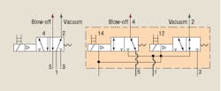
In blow off operations for a machining application, the end user specifies valves to ISO 5599 (-1 or -2) and the tasks are accomplished by blocking ports on 4-way valves in all stations to obtain the on/off control function. Figure 5 shows an application where a 4-way single solenoid valve controlling vacuum and blow-off can have the air consumption of the application considerably reduced using a split spool valve with NO/NC configuration.
In pneumatic part present sensing for a machining application, pressure is applied to specific reference points on a workpiece, which is verified for conformance by monitoring the pressure drop due to leakage. This determines if it is within machining tolerance. ISO 5599 (-1 or -2) standard valves are specified and again the task is accomplished by plugging a port on a 4-way valve.
Summarizing benefits
The development and refinement of split spool valves in the last few years offer additional tools for a pneumatic system designer to save on initial components' costs, reduce the physical size and weight of valve manifolds (and possibly the size of the final machine), and provide reduced maintenance and operating costs for the end user.
Although some pneumatic valve suppliers offer split-spool valves, many users are not aware of them. It is important to recognize that there is no compromise in control and performance. All of these benefits are achieved without sacrificing performance.
For more information, contact the author at (800) 739-7684 or [email protected], or visit www.boschrexrothus.com
