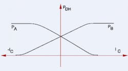
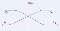
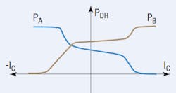
Port pressure gain is the slope of the dead head pressure curve vs control current at a specific operating point as applied to each of a valve's two work ports.Pressure metering curves are assessed with work ports dead headed. In servo-valves, the pressure metering region is confined to approximately the center 5% of spool travel. For overlapped valves, pressure metering takes place over the entire dead zone, and more.
Referring to Figure 1, pressure gain is calculated as:
GP,A = dPDH / dIC
where GP,A is pressure gain,
PDH is dead head pressure at the particular valve work port, and
IC is the control current.
Optimally, two pressure measuring instruments can be replaced by a single differential pressure sensor or gage. It is the differential pressure gain that is reported in technical catalogs and literature:
GPD = d(PDH,A – PDH,B) / dIC
where GPD is differential pressure gain,
PDH,A is dead head pressure at the valve's A work port, and
PDH,B is dead head pressure at the valve's B work port, and IC is the control current.
For a servovalve with essentially zero overlap:
GPD = 2 GP,A = 2GP,B.
The pressure gain statement in a servovalve catalog reads as follows:
Pressure gain — The blocked cylinder port pressure changes rapidly from one limit to the other as input current causes the spool to pass through the null region. The pressure gain at null for servovalves exceeds 30% of supply pressure for commands of 1% of rated current, and normally is between 60% and 80%.
The first sentence is simply a comment comment and can be safely ignored. The second contains information needed for a pressure gain calculation.
A review of current valve technical data sheets reveals a variety of ways that pressure gain is stated. Even within a single manufacturer, there can be several different ways to express it. This only adds to the confusion on the part of those who want to use these valves and who could benefit from them. And ISO 10770-1 is silent on this matter, and its developers have missed an excellent opportunity to help standardize not only the procedures, but also the methods of reporting these parameters.
The valve manufacturer must provide a range on the pressure gain, because gain will vary from one valve to another. The reason is very practical: Pressure gain is a function of the amount of overlap, spool-to-bore clearance, metering land corner sharpness, and other results of manufacturing variations, all of which are well within tolerances. When you consider that the land-to-land dimensions and the spool-to-bore clearances are measured in millionths of an inch, it is easy to see how pressure gain can vary so much. In fact, pressure can be an important quality-control check for manufacturers.
Because pressure gain is so sensitive to very minute differences in internal dimensions, it can vary substantially from specimen-to-specimen. The wise designer will always try minimum, maximum and mid-range pressure gains at design time, because pressure gain does affect the application performance.
What about overlapped valves?
Figure 2 shows a "typical" pressure metering curve for a proportional valve that exhibits significant overlap. In proportional valves, with their significant overlaps, pressure metering takes place throughout the entire dead zone. The dead zone is not really dead, because the finite spool-to-bore clearance results in internal leakage. Note, also, that such valves do not fully shut off. There is still some miniscule amount of flow metering too, which results in the actuator creeping very slowly through the null zone. So the pressure metering zone extends over the entire overlap region and even extends somewhat into the region where the lands move into the flowing region.
A general rule is to view the pressure metering zone of an over-lapped valve to cover the width of the dead zone, plus about 5% more of spool travel. Thus, it is possible to have pressure metering from about 10% of spool travel up to about 40% of spool travel in a proportional valve. On the other hand, in the nominally zero-lapped servovalve, the pressure metering zone is confined to about the center 5% of spool travel and may extend to about 10% of spool travel in some valves. Not surprisingly, pressure gain is directly proportional to the supply pressure, but inversely proportional to the dead zone width.
Servovalve null characteristics
The major manufacturing effort in servovalves goes into making the null. Null for the valve is defined as that condition where the differential dead head output pressure is zero. Because the valve has no output flow, all leakage is confined to the valve's four lands.
Certain system parameter changes will cause the null to shift. System parameters that affect the null are:
• supply pressure,
• valve temperature, and
• tank port pressure.
Null sensitivity tests — Imagine a situation where we have set up a valve at a fixed supply pressure, a fixed temperature, and a fixed tank port pressure. Set up will consist of adjusting the mechanical null on the valve until both work ports reach the same dead head pressure while the coil current is zero. The valve is now nulled.
Next, we change one of the three parameters, say, supply pressure. If we increase supply pressure, and if the valve was perfect, it would maintain its null at any supply pressures. But it is imperfect, requiring that we adjust the coil current to a new value in order to re-acquire the null. That change in current is a measure of null sensitivity to (in this case) the change in supply pressure. That value is published for servovalves. Similar figures are published for thermal and tank port pressure null sensitivity.
To design a servo system, you must take into account all the sensitivity factors of the valve in the context of the application. This requires calculating all the expected null shifts as amperes of coil current. Start by understanding the following definitions: SPS is the published sensitivity of the valve null to changes in supply pressure.
S is the published sensitivity of the valve null to changes in temperature.
SBP is the published sensitivity of the valve null to changes in tank port back pressure.
If the valve's manufacturer has published a given sensitivity factor, SX, then the change in current caused by a change, (XAPP) of the affecting parameter is given by:
∆IX = SX × IR × ∆XAPP
where ∆IX is the amount the valve current must change, in amperes, to compensate for the null shift,
SXis the specific sensitivity factor taken from catalog data on the valve,
IR is the rated current of the valve in amperes, and
∆XAPP is the change in one of the three parameters that is expected in the application.
An infomercial from the author
In our continuing quest to disseminate electrohydraulic technology, we at IDAS Engineering Inc. have prepared a 55-minute educational video on a servomechanism. It's on a CD and will play directly on your Windows-based computer. This animated video clearly and graphically describes the dynamic actions that take place when using electrohydraulic feedback control. You can see the command changing and immediately observe the effects on the output of a cylinder. You can even track the control valve current. And perhaps best of all, it is nonmathematical.
What happens to the error in the servo system? You'll be able to examine that, too, and for a small fraction of the time and money I have invested in developing my career around these machines.
This video offers you the quickest and least painful way to gain valuable insights into the operation of feedback control systems as they are applied to electrohydraulic servomechanisms. Colorful motion graphics illustrate the more subtle nuances, such as saturation and timing of valve spool motion.
To order, or for more information, click here to visit the H&P Bookstore and scroll down to Animated Video DVD: Introduction to Electrohydraulic Servo Systems.


