Compressed air is second only to electricity in importance as an industrial energy source, and there is hardly a factory that functions without it. For many industrial applications pneumatics is the preferred drive technology, thanks to advantages such as overload resistance, long life, economy, ease of assembly, reliability, and safety.
Because pneumatic equipment generally operates trouble-free, users often take it for granted and typically do not look for problems or inefficiencies. However, given today’s high energy costs and competitive landscape, smart companies are constantly looking for new methods to improve equipment efficiency as well as eliminate waste. Therefore, it makes sense to pay attention to the proper use of compressed air. One technique gaining ground is to monitor air consumption, as it is a good indicator of the health of pneumatic systems.
However state-of-the-art a pneumatic system may be, undesired increases in air consumption cannot be ruled out. Daily wear-and-tear, particularly on the seals, contributes to leaks, which over time waste money and hurt performance. When systems begin to leak, pneumatic components start to slow down. So users tend to increase system pressure to combat the problem. But adding more compressor capacity means leaks draw even more air, leading to a downward spiral of inefficiency and energy losses.
Besides wasting energy, pressure drops due to leakage could cause pneumatic components to perform below par. The short-term fix of boosting pressure inevitably leads to more serious problems with components, eventually resulting in premature failure. Many users continue to run pneumatic systems until they fail, typically because it is difficult to isolate the process or component contributing to higher air consumption.
The solution
To pinpoint leaks and losses, system air-consumption monitoring should be an on-going process. A leak-detection program is one option that usually involves complete, manual inspection of all air lines. Technicians typically diagnose leaks by listening for hissing air, inspecting tubes, and tightening fittings.
One disadvantage of leak-detection programs is that depending on inspection frequency, leaks can go undetected for a long time. Also, inspections are usually time consuming and may be problematic in noisy industrial environments. Inspectors often miss small leaks, which prevents repairs in the early stages before leakage becomes a major problem.
Continuous life-time monitoring of pneumatic systems is proving to be a better solution, resulting in cost-effective operation and longer equipment life. Limited monitoring and diagnostic audits for specific industry segments have been available but, until recently, there has been no generic tool that provides overall system monitoring, diagnostics, and comprehensive energy savings. Likewise, it has been possible to purchase an array of sensors, controller, and display; write the appropriate software; and assemble, configure, and troubleshoot a custom monitoring system. But the time, trouble, and expense mean such systems are rarely installed.
Energy monitoring
As a better solution, Festo Corp. has developed a tool that monitors system flow, pressure, and air consumption in conjunction with smart flow and pressure sensors, a diagnostic controller, and a user-friendly graphical display. The latter, called a FED (Front End Display), can be combined with an external SCADA (supervisory control and data acquisition) system that permits remote data evaluation. Called GFDM, Festo’s energy-monitoring package comes as a complete system that provides real-time data and in-depth data analysis of machine performance.
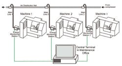
Flow sensors, properly sized and installed at important locations within an air-distribution system, highlight deviations, send messages, and activate alarms when flow exceeds tolerance thresholds. Technicians can easily pinpoint leaks, failures, and other problems and take immediate actions to fix them. In addition, sensors in production facilities can track air consumption of pneumatic systems – even down to specific components – and help calculate true operating costs.
Sensors can be used throughout an entire air system, though the number and exact location depend on customer requirements. Typically some are integrated at important points of the air distribution system and monitor flow to groups of machines. Any increase in air consumption would at least indicate a problem exists and note the general area of concern.
Other users are more interested in monitoring flow to a single machine or individual subsystem. In these cases, sensors quickly narrow the source of any increase in air consumption.
Finally, a single component is sometimes critical to a manufacturing process or operating an entire assembly line. In such cases, it is a good idea to mount a sensor that will closely monitor just that component. A general rule of thumb is to install at least one flow sensor in the main supply line on every machine with an average-size pneumatic system. It tracks air consumption over the long term and easily identifies sudden increases in demand.
If air consumption varies when equipment changes from one process to another, the machine PLC updates the energy-monitoring controller with new operating guidelines. Otherwise, the GFDM package is totally self-sufficient and needs no external interface besides a power supply.
It comes preconfigured to streamline setup for the user. For instance, software to initialize the sensors is embedded in the controller, which also includes analog input modules for flow sensors and digital input modules for communication with the machine.
Customizing the display for an application is straightforward: technicians must input the tolerance settings for flow and air consumption. Once configured, a simple teach-in process can be performed by averaging data over a number of cycles.
The unit also offers several possibilities for archiving or off-line number crunching. Recorded data can be exported into spreadsheets (.csv format) for use with post-processing software. It also archives data for later review. For instance, referencing can capture a “good” condition of the system. The data can then be used to monitor system conditions and can be invoked on-demand for troubleshooting in case of problems. A graphical display provides real-time analysis of flow rates and system air consumption – both through waveform analysis and bar charting. Alarms indicate when user-defined thresholds are violated for up to four concurrent failures.
Each package monitors up to 16 separate processes that can be totally independent from each other. And for recurring processes, a new teach-in is not necessary – previously generated data uploads automatically. This can permit 24/7 operations using a single monitoring package.
Cost savings
Every potential user has one essential question: How much will this package save in my production plant? Here’s an example to show the potential cost savings. Compressed-air losses depend on the pressure and size of the leak path. Let’s assume a production line has 20 leaks of 0.5 mm (0.019 in.) diameter at 6 bar (87 psi), 20 leaks of 1 mm (0.039 in.) at 6 bar (87 psi), and 10 leaks of 2 mm (0.078 in.) at 7 bar (101.5 psi). In reality, conditions are usually much worse, even though plant operators are generally unaware of the losses.
If the plant runs for 6000 hours annually with an electric rate of $0.07/kWh and compressed-air generation requirement of approximately 18 kW/100 cfm, then we can calculate the potential cost savings as follows.
Potential cost savings = number of leaks flow rate (scfm) kW/(scfm) operating hours/year $/kWh.
Cost savings from 0.019-in. leaks = 20 0.49 0.18 6000 0.07 = $740.
Cost savings from 0.039-in. leaks = 20 1.98 0.18 6000 0.07 = $2993.
Cost savings from 0.078-in. leaks = 10 9.24 0.18 6000 0.07 = $6985.
Thus total annual savings from eliminating these leaks is $10,718. Note that this example concentrates only on energy costs and does not consider that leakage and pressure losses usually slow down machines and overall production. It also does not account for downtime caused by failures which could be prevented by early leak detection.
The energy monitoring package has no impact on automation processes, making it easy to integrate into an existing machine. It lends itself especially to evaluating air consumption for different operations, checking the health of pneumatic systems, finding the optimal operating point of a machine, preventive maintenance, and central or decentralized monitoring of air consumption.
The GFDM package is available as a kit or fully functional control cabinet, and also for periodic leasing for condition monitoring. The system helps users optimize compressed-air use at the point of consumption, and develop an efficient maintenance plan which will ensure a considerable return on investment and longer machine life. Data from various projects show that cost recovery for implementing the energy monitoring package would be well within one year.
For further information, contact the author at [email protected], call (631) 435-0800, or visit www.festo.com/us/diagnostics and www.festo.com/us/gfdm.


