Ground testing of hydraulic and pneumatic components installed on aircraft, missiles and unmanned aerial vehicles is critical to ensure flight worthiness. Whether it be a hydraulic pump or valve, accurate flow measurements help determine system performance.
Today’s demanding aerospace market demands implementation of meticulous quality control systems in the manufacturing process so that the final product meets all the internationally set standards. For example, manufacturers of hydraulic and pneumatic components used onboard aircraft or in other aerospace or defense equipment are faced with not only government and military standards, but also industry cooperative standards such as the National Aerospace Defense Contractors Accreditation Program (NADCAP). The goal of standards such as ISO 9000 and NADCAP is to develop basic quality programs that provide for continuous improvement emphasizing defect prevention and reduction of waste and variability.
Demands on manufacturers
The risk to human life inherent to aircraft failure must be a serious consideration for all suppliers of aerospace equipment. The risk factor means the reliability of all systems used to control the aircraft must be given a high priority.
Manufacturers of aircraft components use hydraulic and pneumatic test stands to verify 100% certification of performance and reliability over the part’s full range of inputs. Each component must pass rigorous test procedures before it is shipped to the ultimate customer. Inspection through sample testing is not an option for such a high liability product.
Designers of aerospace equipment are also developing more efficient systems to meet the demands of increased industry competition. Improving designs often includes a review of the hydraulic system, as engineers seek more efficient means of transmitting power. Increasingly, the focus is on reducing the size of hydraulic components or concentrating power into smaller package sizes. This can be accomplished by using higher operating pressures.
During the prototyping of a new helicopter platform, for example, component manufacturers may need to test the performance of an orifice or pump. Flow measurements not only have to be extremely accurate, but data must also be provided on a real-time basis. Once the flow data are collected, the manufacturer makes the necessary design changes, keeping the aircraft within specified performance tolerances.
Common testing requirements
Hydraulic components intended for commercial and military aircraft are typically designed for maximum power density and reliability. Because low maintenance is critical to aircraft of all types, hydraulic component makers continually seek to optimize existing products and systems, as well as manufacturing processes.
Although every component of a hydraulic system undergoes stringent testing, valves, pumps, and actuators are scrutinized especially closely. Liquid flow measurement is commonly used as a fine-tuning process to monitor the machining and assembly of the hydraulic component to achieve the desired flow characteristics.
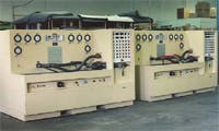
Most hydraulic test stands are dedicated to test one or a limited set of hydraulic devices. These systems, which typically run in either semiautomatic or fully automatic mode, contain a cabinet with flow regulators, pressure regulators, manifolds, and connections to the unit under test. A computerized data-acquisition and control system, along with a full suite of sensors, enables the test stand to perform a variety of tests.
The most widely used technique for precise leakage measurement of aircraft parts is to connect one end of a hydraulic cylinder to the component under test, and the other end to a pressure source. If any fluid leaks from the unit under test, fluid enters from the cylinder to replace it, and the piston moves. Therefore, movement of the piston over a known time period is a measure of the leakage rate.
Latest flow meter technology
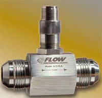
For test stand applications requiring the best flow measurement accuracy available with the benefits of high resolution and dynamic response, proven reliability and compact size, a precision turbine flow meter is the flow sensor of choice. The high resolution of the turbine meter makes it ideal for detection of leaks in aircraft fluid systems. With resolutions to 48,000 ppg (pulses per gal) for small turbines, minute fluid flow can be detected.
A turbine flow meter paired with a flow computer can be used to measure the hydraulic fluid flow through a component under changing conditions. Tests can involve multiple types of hydraulic oils, each having unique characteristics related to temperature, pressure, and viscosity.
Turbine flow meters rely on a proven, highly accurate measurement technology, which provides exceptionally reliable digital outputs. These flow meters incorporate a freely suspended turbine rotated by the flow of the fluid (liquid or gas) through the meter body.
Because the flow passage is fixed, the rotor’s rotational speed is a true representation of the volumetric flow rate. The rotation produces a train of electrical pulses, which are sensed by an external pick-up mounted directly above the rotor. The frequency of the pulses can be converted to an analog current or voltage or can be displayed as gpm, lb/hr, cfm, or in other engineering units.
The 2- to 3-msec response times typical of turbine flow meters provide rapid updating of flow rate. Furthermore, calculations are made in conjunction with real-time temperature, pressure, viscosity, and density values — which lends itself to output as mass flow rate.
Turbine flow meters also have a relatively high turndown ratio, with a linear range of 10:1 and a repeatable range of up to 100:1. This capability often enables a single turbine meter to replace multiple meters with a lesser turndown capability and can significantly reduce cost in applications requiring accurate rate and totalization measurement over a wide flow range.
Unlike other flow sensing technologies, turbine flow meters are compatible with remote electronics. Also, when paired with a heat-tolerant electronic pickup and amplifier, turbine flow meters can be located in areas exposed to extreme temperatures. In this setup, data acquisition electronics are safely mounted elsewhere.
Data accuracy
Depending on the accuracy requirements and flow conditions, primary standard flow meter calibration techniques alone may meet the application requirements. When accuracies to ±0.012% reading are needed, advanced flow electronics and calibration techniques can be used to provide volumetric or inferred mass flow outputs.
The combination of a precision turbine flow meter and advanced flow electronics provides a solution for measuring bi-directional flow in hydraulic and pneumatic testing. Flow measurement performance is optimized by compensating for viscosity changes from variations in ambient fluid operating temperature, which affects the accuracy of liquid flow data.
In hydraulic test stand applications, a turbine flow meter with a bi-directional Universal Viscosity Curve calibration can be equipped with pickups for determining flow direction and sensing temperature. The turbine meter may be paired with a flow computer, which performs linearization and temperature compensation to ensure high accuracy over the meter’s full extended range. The unit’s electronics can be configured to display volumetric or mass with temperature compensation for variations in liquid viscosity and density due to temperature. Such flow computers simplify test procedures by storing temperature versus viscosity and density data for multiple fluids — saving time to boost productivity.
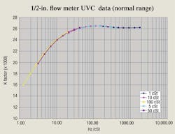
In order to correct for viscosity changes in the hydraulic fluid, the relationship of temperature vs. viscosity for the fluid and the operating temperature range of the measurement must be known. With the operating kinematic viscosity range known, the turbine flow meter is calibrated at multiple viscosities spanning the operating range. The flow meter will require a calibration for every factor of ten that the viscosity changes.
For example, a fluid with an operating range of 1 to 100 cSt would require a multiple point calibration at 1, 10, and 100 cSt. These data are then calibrated on a universal viscosity curve, which is formed by plotting the flow meter’s K factor on the linear scale and frequency divided by kinematic viscosity on the logarithmic scale. The result of this plot is one continuous curve covering the range of possible meter frequencies and viscosities.
Conclusion
Aircraft equipment manufacturers require state-of-the-art flow instrumentation for use in component test environments. Turbine flow meters have long been the choice for aerospace and defense industry testing. They are accurate, have a wide turndown ratio and fast speed of response, and, when paired with advanced flow electronics using universal viscosity calibration techniques, can be employed over a wide range of temperatures and viscosities.
Ladd Howell is aerospace applications engineer at Flow Technology Inc., Tempe, Ariz. For more information, visit www.ftimeters.com.
Learn more about the Navy's BAMS now: