To provide the required reliability and maintainability, the 727 has dual hydraulic systems. In addition, a smaller, isolated standby system offers an alternate power source for the leading edge slat and flap system. Also, the standby system is the third power source for the rudder, because the rudder does not have a manual backup system controls. All three systems use Skydrol 500A and operate at 3000 psi. [Editor's note: Skydrol 500A was was deemed obsolete and discontinued in 1969.]
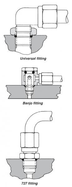
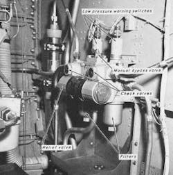
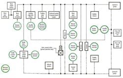
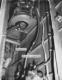
Plumbing Improvements — Equipment studies showed the need for considerable improvement in tubing fittings, hose materials, and static and dynamic seals. Improved pump life and reliability were also desirable. Leaks at tubing fittings were attacked in two ways. First, universal type fittings, using locknuts and O-rings, and banjo fittings were eliminated. Instead unions and tube bends and angled fittings on flex lines are used, Figure 1. Second, the 727 has about 20% fewer tube assemblies than normally used on a system of this size. Tube assemblies were eliminated by grouping components into modular assemblies, Figure 2. All components are cartridges, which are assembled into the modular housing. Any cartridge can be removed without removing the modular assembly from the airplane. Also, this largely eliminates disassembly of tubing joints. A study of fabrication and tooling used on previous aircraft resulted in closer control, better tooling for the manufacture and installation of tubing, and tighter control of material for tube assembly components.
Tubing in the high-pressure system is installed with MS flareless fittings and tube nuts of steel. Aluminum alloy MS flareless fittings are used in return and supply lines less than 1.0-in. OD, and aluminum alloy NAS flared fittings are used on return and supply lines of 1-in. OD and larger. Cold-drawn, corrosion-resistant steel tubing is used in the 3000-psi systems and on the landing gear. Seamless 6061 T-6 is used in return and supply lines less than 1.0.-in. OD, and 5052-0 tubing for 1.0-in. OD and larger. All fittings are installed by measuring torque to ensure uniform tightening of the joints.
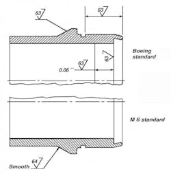
Because tubing joint leaks had been a major maintenance problem, we examined the components involved and the fabrication processes for possible improvement. New tooling was developed to ensure uniform sleeve pre-setting. Also, a new sleeve standard was established to provide better material and finish control. The new sleeve standard gives better material control, closer tolerances on case-hardened depth, and improved finishes. To obtain uniform heat treat throughout the sleeve, only a non-leaded, low sulfur, carbon steel is used. Also, the case and core hardness tolerances were tightened to ensure a uniformly good ring cut.
The MS standard required a good machine finish only on the surface in contact with the nut. In order to be consistent with the MS fitting sealing surface, we controlled the finishes on all sealing surfaces on the sleeve, as can be seen by comparing the MS and BAC standards in Figure 3.
New Seal Developed — Both static and dynamic seals had been a perennial problem, particularly on passenger jets, because elastomers are not available that are completely compatible with Skydrol 500A. They do not possess the required resilience, abrasion resistance, and volumetric stability. However, ethylene propylene, a recently developed rubber, appears to have the required properties. EP rubber being phased in for all elastomer seals in the 727 hydraulic systems.
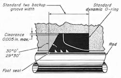
An extensive dynamic seal program was carried out to provide a long-lived, rugged, dynamic seal, particularly for flight control units. The result was the foot seal composed of a Teflon element and an O-ring installed in a split gland, Figure 4. This gland seal is used in all actuators and in all landing gear sequence valves. Generally, piston seals are solid Teflon rings in pairs backed by a marcel spring.
Teflon Hose — All hose assemblies are Teflon-lined, exposed wire braid type with swaged-on couplings. The swaged·on coupling was chosen after considerable study and tests had shown it to be the tightest joint and most fool-proof proof for assembly and installation.
Experience shows that the longer life of Teflon hose more than offsets its higher cost. Also, Teflon hose has an unlimited shelf life, eliminating age dating of spare stocks. Where abrasion of adjacent structure is a problem, the hose is jacketed with polyolefin heat-shrink tubing
Pump Choice — Customers may choose either of two engine-driven pumps currently being used on the 707 airplane These are well-proven pumps with several hundred thousand hours of service.
Because flow requirements for System B (primarily a flight control power system) exceeded capacity of the 707 electric-motor-driven pump, a new specification was developed for a 6-gpm motor pump. Two electric-motor-driven pumps designed to this specification were developed and tested. One is a redesign of an existing pump to adapt it for use with Skydrol 500A, plus a redesign to add recirculating lubrication in the gear box. The other is the outgrowth of two design objectives in the motor pump requirements: one, that the motor pump have no external dynamic seals, and two, that the gear box be eliminated. Either pump is installed on airplanes at the customer's option.
Filter Design — Another area that merited considerable attention was filtration, particularly of fluid flow into and out of pumps. Here, again, we drew from 707 experience with both paper and metallic element filters that showed metallic elements to be better. All filters installed in the lines to and from 727 pumps have metallic elements with 10-micron nominal, 25-micron absolute ratings. Filters in the pump case drain and pressure lines are non-bypass type.
Case drain filters contain magnetic plugs with self-closing valves, so plugs may be withdrawn for inspection without spilling fluid. The amount of metallic particles collected on these plugs provides a convenient way to periodically check the pumps' mechanical condition. System return filters have a relief valve set at 100 psi to ensure that no fluid bypasses during normal operation. Filters in the pressure-filling system also contribute to improved pump life by assuring a clean fluid supply.
Testing Program — To demonstrate performance and reliability of the hydraulic system and components, extensive laboratory and flight test programs have been carried out. The flight controls test setup simulates the airplane from control column to control surfaces. The two major laboratory test setups were the landing gear retraction system and the flight controls system. The landing gear test setup includes a complete left main gear and nose gear to evaluate impact noise, maximum operating pressure, and operating times. Following these tests the two gear systems were cycled 30,000 times, equal to about ten years of operation.
All three hydraulic power systems have components and tubing installed as they are in the airplane. Instrumentation records temperature, pressure, and flow data. The setup ensures that all hydraulic systems are properly coordinated to give smooth transfer from one to another. It also serves to life cycle flight control components.
The flight test program — The real proof of design-includes recording instrumentation for pressure, temperature, and flow. No serious problems were encountered during approximately 1000 hours of flight testing. The 727 has gone into airline service without any difficulties in the performance of the hydraulic system.
A tale of two systems
The Boeing 727 jet has two operating hydraulic systems plus a third, standby system. All three use Skydrol 500A and operate at 3000 psi.
System A is the utility system which operates the landing gear retraction system, nose gear steering and brakes, leading edge slats and flaps, trailing edge flaps, ground spoilers, and half of the flight spoilers. In addition, it provides one of the hydraulic power sources for the ailerons, rudder and elevators. Two engine-driven pumps installed on accessory pads of the number one and number two engines supply hydraulic power. The reservoir is pressurized to 45 psi by engine bleed air routed through a combination pressure regulator/relief valve. Case drain cooling fluid from the two engine-driven pumps is brought together and routed through a fluid-to-fuel heat exchanger in the right fuel tank, then returned to the reservoir through the return system filter.
The B system, primarily a flight control power system, provides one of the power sources to operate the ailerons, elevators, and rudder, as well as inboard flight spoilers, main wheel brakes, and aft passenger entry stairs. Two electric-motor-driven pumps supply power. Cooling fluid flow from the pumps runs through case drain filters, then through a fluid-to-fuel heat exchanger in the left fuel tank and back to the reservoir. All components associated with the B system are conveniently located in a compartment with access through a large door.
Reservoirs Connected — The A and B reservoirs are connected by a balance line from the top of the B reservoir to a point above the minimum operating level on the A reservoir. This permits both reservoirs to be pressurized simultaneously. On the ground only, the balance line also serves as a return line, permitting the B system pumps to pressurize all A system functions, by means of a system interconnect valve.
A pressure fill in the B system compartment services all three reservoirs. Fluid may be pumped into any reservoir through a selector valve with a hand-operated pump, or from a filling cart through a disconnect adjacent to the hand pump. Fluid from either source passes through a filter before entering any system reservoir.
The standby system equipment is accessible from the aft passenger entry stairs. It is a second power source for the leading edge slat and flap system. It is the third power source for the rudder, which cannot be operated manually. The system contains a motor pump, reservoir, fluid level indicating system, filters, and a pressure indicating system.
James E. Klansnik is Hydraulic System Group engineer at The Boeing Co., Seattle.
This article was originally published as "727 jet hydraulics: MORE and BETTER," in the July 1964 issue of Hydraulic & Pneumatics. It is reprinted here for its archival value and reader interest.
