This file type includes high resolution graphics and schematics when applicable.
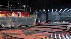
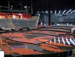
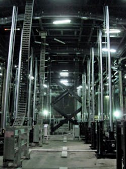
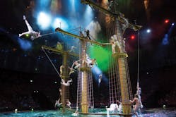
Taking in Franco Dragone’s The House of Dancing Water production in Macau, China’s City of Dreams, is breathtaking. Sophisticated staging is actually composed of eight different lift sections. The stage (Fig. 1) sits atop a forest of hydraulic cylinders (Fig. 2) that lift and lower the sections up to 27 ft. in the world’s largest indoor swimming pool. At times the lifts are raised to form a dry stage and at other times, they independently recede to produce a water pool for swimmers, only to emerge again carrying large props such as a pagoda structure (Fig. 3) and a 26-ton ship (Fig. 4).
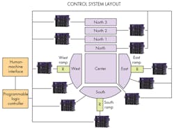
The cylinders are controlled by a bank of 11 RMC150 electrohydraulic motion controllers (Fig. 5) manufactured by Delta Computer Systems. Four hydraulic cylinders (mounted symmetrically underneath) actuate each main platform section—for a grand total of 32 motion axes controlling the main platform sections. Another 18 axes operate three performers’ entry and exit ramps (each ramp, called a vomitorium, has six axes of control for lift, extension, and tilt). All main platform cylinders are controlled by remote valve manifolds located in the basement of the theater beneath the pool, and the cylinders are mounted to the pool floor inside submerged concrete caissons.
Because the theater is constructed with separate water-holding and dry enclosures, the hydraulic valves and cylinders are located a distance apart, with a large amount of hydraulic oil (on average 70 gal) in each cylinder and in the plumbing between the cylinder and its valve. To keep the platform sections level and avoid deforming the structural frames, motion of each cylinder operating a lift must be tightly synchronized with each other. This requirement is made even more challenging by the compressibility of the volume of hydraulic oil between each valve and cylinder.
To provide the hydraulic components for this large and complex application, Controlled Motion Solutions (Comoso), Santa Ana, Calif., was hired by the general contractor, Handling Specialty of Grimsby, Ontario, Canada. Comoso’s system engineering manager, Matt Schoenbachler, headed up the design of the overall hydraulic system and all associated hardware. The team worked with Parker-Hannifin to design custom double-acting cylinders to control the platforms.
Each cylinder has an 8-in. bore with a 7-in. rod and a 324.8-in. (27 ft.) stroke. The cylinders are fed by Parker servo-quality proportional valves. To provide a measure of its position, each cylinder is instrumented with a 27-ft. long magnetostrictive linear displacement transducer from MTS Sensors. Hydraulic fluid to operate the system is pumped from a 3,500-gal reservoir by 21 Parker PV variable-displacement piston pumps and T7 fixed-displacement vane pumps. In total, the pumps can deliver up to 1,671 gpm of pressurized fluid. The pumps are driven by seven electric motors that can transmit up to 2,100 hp.
Accounting for Compliance
As mentioned earlier, synchronizing the motion of the multiple cylinders operating each stage panel provided challenges to the designers. “Because of the compressibility (compliance) of the large volumes of hydraulic oil contained in the plumbing and cylinder assembly itself, we understood that a simple PID control algorithm would be difficult to tune in this application, and only a Delta Computer Systems controller would have a chance of providing favorable results,” says Schoenbachler. Even with control loop gains set to low values, starts and stops could still cause the system to oscillate.
The team’s software developer tuned the system in consultation with Delta Computer Systems engineer Dennis Ritola. The team solved the problem by augmenting a proportional-integral-derivative (PID) algorithm in the motion controller with an additional control equation factor in order to avoid the oscillations. “We avoided the oscillation problem by adding a second derivative gain term to the control equation to compensate for the springiness of the system,” says Ritola.
Introducing the second-derivative gain element requires that position feedback information be converted to measured accelerations. However, doing so can “create” significant high-frequency noise in the measurements and the resulting control output. “In this case, to cancel the output noise effects, we recommended adding a low-pass filter to the control output that drives the valves,” explains Ritola. “This eliminated the output noise and allowed the control axes to be properly tuned.” When the process was finished, the stage platforms moved and positioned smoothly with no oscillations.
Solving Another Challenge
In addition to compensating for the capacitive effects of the long hydraulic lines, the controllers must compensate for dynamic changes in the loads on the cylinders as a lift floor breaks the surface of the water in order to keep the motion of the lifts smooth. The challenge is dealing with the buoyancy of the platforms. As a platform moves up out of the water, its effective load increases because it is no longer counteracted by the buoyancy from the water. The system design specification dictates that the extensions of the cylinders operating any lift never differ by more than 5 mm dynamically, while moving at a rate of 4 in./sec.
To coordinate the motion of the multiple axes operating each panel, the controls engineering team set up the motion controllers to use a special synchronization function that allows some or all of the axes that the motion controllers to be configured as slave axes, under the control of a master axis or a master input coming from an outside control source. In the Dancing Water system, the motion of each lift cylinder is tightly controlled by an RMC as a slave axis following commands from a master PLC.
Feedback of Linear Position
The motion controllers receive cylinder position feedback from the magnetostrictive linear displacement transducers (LDTs) that are mounted inverted alongside the cylinder bodies, with the controls on the rod side and the sensing probe extending down toward the cap of the cylinder. This orientation allows easier removal and repair or replacement than if they were mounted inside the cylinders. A stainless-steel rod and magnet carrier is attached to the cylinder’s rod clevis that carries the magnet up and down the sensing element of the probe pressure tube. The LDTs, each situated in a watertight housing, interface to the RMCs in the dry area under the pool via synchronous serial interface using waterproof cabling, seal glands, and connectors.
Another interesting aspect of the magnetostrictive LDTs was pointed out by Mike Wardle of MTS Sensors Division. He said the maximum length for the standard rigid sensor, in general, is 300 in. (25 ft.). So the 27-ft. requirement for this application demanded an alternative. Wardle said the standard maximum length for a flexible sensor is 10 m—32.8 ft. This meant a standard flexible sensor could be used and held rigid inside the watertight enclosure. Additionally, these flexible sensors are easily coiled, packaged, and shipped more cost effectively.
The flexibility and smooth motion enabled by the motion controllers far exceeded the expectations of the show’s production staff. “Initially, the staff was hoping to be able to position the stages in some simple configurations, but they learned that through the precision and programmability of the hydraulic controls more special effects were possible,” says Comoso’s Schoenbachler. “We believe that our system gave Franco Dragone the capability to produce more dynamic moves in making an even more spectacular show.” And as an indicator of the robustness of the hydraulic system, The House of Dancing Water show has been delighting audiences for more than five years.
Take a behind-the-scenes look at the staging:
Looking for parts? Go to SourceESB.
This file type includes high resolution graphics and schematics when applicable.
