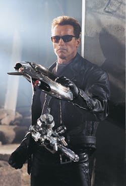
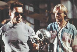
Arnold Schwarzenegger returns to the screen in the latest sequel to The Terminator. But don’t plan on seeing him at your local theater or expect this production ever to be released on home video. That’s because Terminator 2 3-D, Figure 1, is playing only at Universal Studios Florida. And like the other attractions at Universal Studios Florida, Terminator 2 3-D is not something you sit passively and watch — you experience it.
This latest sequel reunites Schwarzenegger with former costars Linda Hamilton as Sarah Connor, Edward Furlong as young John Connor, and Robert Patrick as T-1000, the morphing metal menace. Joining this cast is a host of new villains, including a fleet of Mini-Hunter-Killers and T-1,000,000, which is entirely computer generated and exceeding in complexity than anything that had been done to date.
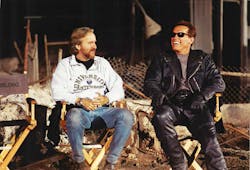
Directed by John Cameron (who also directed The Terminator), Terminator 2 3-Duses the latest in digital imaging technology to catapult the audience into the center of 3-dimensional action right alongside international superstar Schwarzenegger. Sharing in directorial credit are special-effects wizards Stan Winston (Jurassic Park) and John Bruno (True Lies). With a production cost of $60 million, the 12-minute film is, frame by frame, the most expensive live-action movie ever produced. Cameron commented that he regards Terminator 2 3-D as a true sequel to his blockbusters. “It’s definitely the next film. The only difference is this film is only 12 minutes long, and you can’t see it in just any theater.”
Terminator 2 3-D departs from convention in that it is presented in a three-dimensional format, so many of the images appear to pop out of the screen. The production is simultaneously projected onto three 23- by 250-ft screens oriented 60° from each other to envelop the audience. But perhaps the most impressive feature of Terminator 2 3-D is the addition of live actors and an in-theater set that incorporates the audience into the action to add an even greater dimension to the attraction. The electrifying nature of the stunts is typified by a sequence featuring Schwarzenegger driving a 1500-lb Harley Davidson “Fat Boy” that explodes off the screen and roars onto the theater’s stage.
Transition sequences proved to be the trickiest elements of the three-act show, requiring split-second timing to seamlessly unite stunt actors flying out of trap doors in the stage and screen with filmed elements that boasted their own special effects. Producer Chuck Comisky revealed that, “Working out the timing of the screen-to-live elements was our biggest challenge. There are so many variables in a live show, while the movie part is essentially locked in. Yet, somehow, we have to ensure it all works together — every time.”
Pulling it off
Terminator 2 3-Dmerges innovative fluid power, electronic, and mechanical motion-control techniques hidden from the audience’s view to accomplish many of the fast-action scenes. Scenic Technologies Inc., New York, was contracted to develop a technique to permit split-second opening and closing, raising, and lowering of various rigging to achieve a number of live-action visual illusions and to accomplish these effects without alerting the audience to how they were done.
The primary challenge was how to execute rapid linear motion within a half-second time limit to avoid tipping off the audience as to what was happening. A hybrid solution was derived, involving PLC control of hydraulic and pneumatic actuators driving a series of mechanical pulleys and cables. Engineers at Scenic Technologies originally proposed a concept using a high-power servomotor, an electromagnetic clutch, belt-driven linear actuators, spring-mounted guide wheels, and specially machined tracks. In addition, special safety provisions had to be met, which added extra rigging and other mechanisms. This solution met Universal’s original design goal of a full 6½-ft traverse within 1 sec.
In an effort to further enhance the illusion, Universal’s show designers cut the traverse time for lighter objects from 1 to ½ sec. The final design uses a high-speed, servo-controlled, double rod-end hydraulic cylinder rigged with multiple lines of high-strength wire rope. This enables full traverse of heavy objects in a little less than 1 sec.
Pneumatics to the rescue
A combination of pneumatic actuators and mechanical pulleys mounted to the building’s structure move other, lighter objects simultaneously but semi-independently at full traverse speeds within a half second. By adding some smoke, flames, sound effects, and pumping music, guests never know how the magic trick is pulled off.
Lighter objects had to be moved 6½ ft and be synchronized with movement of heavier objects described above. A double-rod end cylinder with pulleys arranged in a block-and-tackle configuration was chosen to cut the cylinder stroke in half while doubling the effective speed. The double-rod end cylinder solution proved ineffective in this instance, however, because of the high torques that would be developed. Further, the external bearing arrangements necessary to prevent rotation would have overcomplicated the rigging.
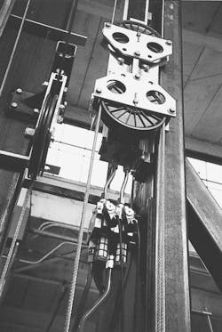
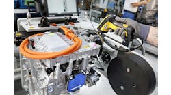
According to Steve Sywak, project engineer at Scenic Technologies, Festo's DGPL non-rotating guided rodless cylinders, Figure 2, were selected instead. These cylinders provide an ideal solution, offering extra-long strokes and maximum travel within their own length. In addition, the barrel of the DGPL cylinder offers enough structural strength to eliminate the need for external structural fixturing. The integral ball-bearing slide connected to the cylinder’s drive yoke provides a simple means to connect the pulleys.
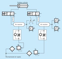
High speed is essential in achieving this particular illusion. Because pneumatic cylinders normally are designed for travel speeds between 4 to 60 in./min, Festo project engineer Daniel Sandoval proposed using a combination of pre-exhaust and air reservoirs to increase piston travel speed to achieve the exceptionally fast 42 in./sec travel required. This solution, Figure 3, proved to be the key to the success of the design.
A 3/2-way valve at each end of the rodless cylinder allows simultaneous control of pressurization and exhaust. Normally, a 5/2-way valve would be sufficient and less expensive, but would not permit pre-exhausting of the cylinder. Four reservoirs (shown in the inset photo on the front cover) were added to the circuit — two near each valve — to compensate for pressure line losses and for the pressure drop that occurs as the cylinder extends. Pre-exhausting the cylinder provided virtually zero resistance to the piston when it was pressurized. This made hydraulic shock absorbers necessary at each end to of the stroke to maximize cushioning and minimize piston impact.
Finally, timing of the sequence and all safety controls are coordinated by the PLC via sensors. Pneumatic/electric pressure switches are used to warn of unexpected pressure drop in the reservoirs, allowing human intervention in the sequence if necessary.
Richard Day, deceased, was marketing manager, Festo Corp., Hauppauge, New York, when this article was originally published.
