Most manufacturers of fittings for high-pressure hydraulic applications agree that O-ring-sealed, straight thread fittings made according to SAE Standard J 514 are the most practical for tubing sizes to ¾-in. OD. Some experts may argue that these fittings are suitable for tubing up to l-in. OD. However, the consensus among manufacturers is that use of hydraulic flange fittings leads to more effective and efficient assembly of larger-diameter tubing.
Two compelling reasons build a strong case for switching to flanges when using larger-diameter tubing. First, tubing larger than l-in. OD would have to be made with very large hex heads, which, in turn, requires very large wrenches so that workers can apply the torque needed to tighten the fittings to specs. Second, designers would have to provide the necessary space to give workers enough room to swing these large wrenches when installing such large fittings. Also, wrench extensions (cheater bars) are often needed for workers to exert enough torque to tighten the hex nut. On top of that, worker fatigue may come into play.
Working with flanges
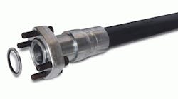
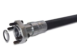
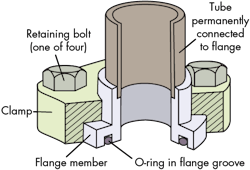
The basic hydraulic flange fitting consists of:
- ÂA flanged member connected permanently to a tube, tubing assembly, or tubing portion of a hose assembly by means of brazing, welding, or mechanical deformation.
- ÂAn O-ring that fits into a groove machined in the end face of the flange.
- ÂA clamp with appropriate bolts that secure the flange assembly to a mating surface. Split flanges, which have a two-piece clamp, are often used because they can be installed or removed without having to slide them on or off from the opposite end of the hose or tube section.
Installation
When installing flanges, all surfaces must be clean and smooth. In terms of critical perpendicular relationships, all parts must meet appropriate tolerances. Although 64-µm surface finishes are acceptable, most manufacturers prefer and recommend 32-µm finishes on mating surfaces to ensure leak-free connections. Joints will likely leak if either of the mating surfaces is scratched, scored, or gouged. Also, O-rings tend to wear faster if assembled against rough surfaces.
This file type includes high resolution graphics and schematics when applicable.
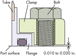
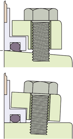
In a properly designed split-flange assembly, the flange shoulder protrudes about 0.010 in. to 0.030 in. beyond the clamp face to ensure adequate contact and seal squeeze with the mating face. The clamp does not actually come in contact with the mating surface.
After a worker establishes that all of the mating parts are clean and suitable for installation, the O-ring must be lubricated, usually with system fluid or a light grease. This step helps keep the O-ring in place and prevents it from falling out during assembly.
The most critical phase in assembling a flange assembly is to tighten the four bolts gradually and evenly to ensure uniform tension among the bolts holding the joint together. The first step is to finger-tighten all bolts. Should one of the bolts be tightened fully while others are still loose, the mating surfaces will not be parallel. This will likely pinch the O-ring, compromising the integrity of the seal. Likewise, over-tightening the bolts can cause them to deflect downward until they bottom on the port face. This lifts the flange off the mating shoulder, raising the potential for leakage.
To overcome these potential problems, it’s best to gradually and evenly torque the bolts in a "cross" pattern. Air wrenches should not be used, because they are difficult to control and can easily over-tighten a bolt inadvertently.
If an O-ring becomes damaged, it must be replaced. The replacement O-ring must be the correct size and made of material compatible with system fluid. If there’s a delay in making the connection, the finished surfaces should be protected while the pieces are being stored with a closure plug.
Information for this article was provided by Anchor Fluid Power Inc., Brennan Industries Inc., Main Mfg. Inc., and Tompkins Industries.
