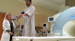
When you go to a hospital or clinic, you expect everything to be not just clean, but spotless. Therefore, you might think we use tap water in the hydraulic system of treadmills that operate in magnetic resonance imaging (MRI) facilities because tap water is clean, so any incidental spills or leaks would be of little consequence. That’s true; when it comes to environmental friendliness, it’s hard to beat plain old water. But that’s not why we use it.
We use fluid power because MRIs in clinical use generate powerful magnetic fields — typically 1.5 to 3 Tesla. Consequently, anything attracted by magnetic fields could be pulled toward the MRI’s magnets. Furthermore, anything that can produce magnetic fields — such as electrical current flow — can interfere with the MRI itself. Therefore, the treadmill cannot contain any ferromagnetic materials or electrical components and must use non-conductive hoses and other components.
Obviously, we couldn’t use electric motors or solenoids in the treadmill. That left us with a choice between hydraulics or pneumatics. Pneumatics was briefly considered, but issues with compliance (compressibility) and noise seemed too significant to overcome within application parameters. Therefore, hydraulics became the obvious choice. But hydraulic motors are usually made of ferrous metals, so those were ruled out. We then focused on stainless steel hydraulic motors and found that those that fit our application parameters were designed to use water as the hydraulic fluid.
Hydraulic drive
Typical exercise treadmills are powered by a variable-speed electric motor for the belt drive and a second electric motor for elevation control. Standardized multistage cardiac stress tests typically call for treadmill belt speeds starting at about 1.7 mph, with increases every 3 min to a maximum speed of 6 mph. Elevation begins at a 10% grade and eventually increases to a maximum of 22%.
The motor’s operating speed ranges from about 500 rpm to more than 3000 rpm. As it turns out, torque requirements for this application are highest at the lowest speed and decrease steadily as speed and elevation increase.
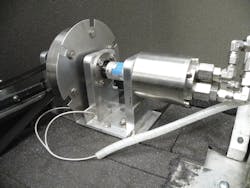
This is a perfect application for a variable-displacement motor. However, we could not find any in the size range and the specific materials required for the MRI-compatible treadmill. The elevation actuation system for the treadmill was straightforward to design and source because stainless steel cylinders are readily available. However, finding a source for a stainless steel hydraulic motor to drive the treadmill belt was more difficult, and we could not find any with a variable-speed option. We chose a fixed-displacement, axial-piston motor constructed of stainless steel and high performance polymers. Supplied by Water Hydraulics Co., East Yorkshire, England, the motor is designed to operate with tap water.
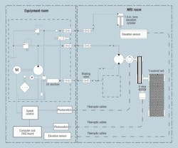
The hydraulic system’s power unit is located in an equipment room adjacent to the MRI room, shielded from the MRI critical environment. Choosing a prime mover and pump was the next challenge. Our fluid limited the pump choices to materials and components tuned to water, even though the equipment room has no limitations on ferromagnetic materials. A constant-speed electric motor coupled to a variable-displacement pump was considered, but again, we could not find a variable displacement pump scaled for our application.
We selected a fixed-displacement axial-piston pump similar in construction to the treadmill’s hydraulic motor. Because the pump and motor have fixed displacement, this dictated a variable-speed prime mover with high torque capability at low speed and low torque demands at high speed. A 3-phase ac motor — rated at 3 kW — was selected. The speed of the motor is regulated by a variable-frequency vector control.
Variable-speed controls
Radio frequency (RF) interference limitations were established because MRI devices depend on a highly shielded RF environment. Control components located within the MRI room itself must be completely free of electrical components and free of electrical conductors between the MRI room and the adjacent power unit. However, the treadmill control system must be linked to other diagnostic software. System status monitors are required to display in the MRI room and log system performance data.
Therefore, we chose fiber optic devices to meet the needs of speed feedback, position sensing, and emergency stop control. The fiber optic cables selected are non-conductive, and all electrical devices are located in the power unit, isolated from the critical environment. Optical feedback from the treadmill is converted to electric signals and communicated to the motor controller and data acquisition (DAC) board.
The hydraulic pump and motor are plumbed for open-circuit, unidirectional operation. Therefore, except for the classic variations in the pump and motor’s volumetric efficiency, belt speed is proportional to the prime mover speed. The treadmill’s belt speed control proved the most challenging control issue. We measure hydraulic motor output speed using an optical rotary encoder, which provides a fiber optic feedback signal that becomes an analog input to the electric motor drive. The variable-frequency vector control is programmed to compensate for changes in load and volumetric efficiency of the pump and motor.
The treadmill’s incline is achieved by controlling fluid flow to an elevation cylinder. The cylinder was designed and manufactured by Lehigh Fluid Power Inc., Lambertville, N. J. Made of 316 stainless steel, it has a 1½-in. bore and 4½-in. stroke. Fluid is supplied to the cylinder by an accumulator, which stores enough pressurized fluid to raise the front of the deck to its maximum incline. The accumulator is precharged with nitrogen and is pressurized to maximum system pressure at the beginning of each stress test by diverting pump output to the accumulator circuit.
Cylinder displacement is controlled by two, 2-way directional control valves (DCVs) and fiber-optic position feedback. The DCVs are not proportional, but they are subjected to pulsed input signals when the error signal is small. This scheme was developed to reduce the overshoot encountered in early testing.
Treadmill testing
Initial prototype testing began outside an MRI room to match performance to established speed and gradient combinations. We expected belt speed and elevation to stabilize within ± 5% of required values. Sensors and software interlocks also included component maximum speed limits and other safety concerns.
Testing was conducted to ensure that the MRI environment did not influence the operation of the treadmill and controls and that the components of the treadmill could be safely located within the MRI’s magnetic field. A 0.7 Tesla permanent magnet was used to test all individual components of the treadmill for magnetic attraction. The completed treadmill assembly was also tested for magnetic attraction.
Additionally, we tested the machine to ensure it would not influence the quality of images recorded during diagnostic tests. A series of standardized tests was conducted to measure image quality comparing the image quality with no treadmill in the MRI room, to a fully connected, stationary treadmill located close to the magnet, and, finally, to an operating treadmill.
Water as a hydraulic fluid
Water is the fluid of choice primarily because the hydraulic motor was designed specifically for use with water. Water has many positive attributes as a hydraulic fluid, but also some challenges. Water is inexpensive and readily available. Its viscosity is significantly lower than oil’s, so water can transmit comparable power with lower pressure differentials, resulting in potentially higher overall efficiency. Even though leakage has not been an issue, water leaks in a hospital setting are less dangerous and easier to clean up than oil leaks are.
Of course, these advantages are offset by some disadvantages. Water’s low viscosity means it flows more readily through small clearances typically found in hydraulic components. Therefore, pumps and motors generally exhibit higher internal leakage, which translates to lower volumetric efficiency.
Unlike oil, water does not readily establish full-film (hydrodynamic) lubrication. Water also can be corrosive to metals and cause erosive wear. Water can be breeding grounds for bacteria and other micro-organisms. Antimicrobial agents can be added to the water to inhibit microbial growth, but we chose, instead, to install an ultraviolet sterilizer in the return flow piping to reduce microbial growth. This does not eliminate microbial growth, so periodic water and filter changes are required.
The current state
The initial treadmill prototype served its intended function by meeting performance goals and providing a platform suitable for clinical research on a limited scale. Many minor changes to hardware and software were required to meet specifications and provide reliability.
Based on the success of the initial prototype, a next generation treadmill design has been built to conduct a multicenter clinical trial. Attention to details of clinical ergonomics, software convenience, enhanced performance, and improved serviceability were incorporated into the new design.
In addition to being Associate Professor, Engineering Technologies at Ohio State University’s Agricultural Technical Institute, Wooster, Ohio, John Arnold, P. E., is also Chief Technology Officer of XCMR Inc., Columbus.
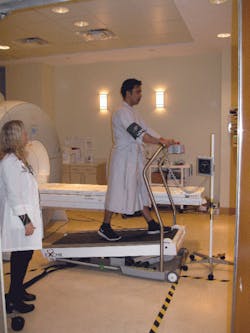
Watch a video of the treadmill setup below:
Why so close?Eric Foster is COO of EXCMR Inc., Columbus, the company that designs and manufactures the water hydraulic treadmill. He explains why the treadmill must be so close to the MRI machine: Heart disease affects more than 70 million Americans and is the leading cause of death in the United States. Two-thirds of these deaths occur without detection of the disease. Treadmill exercise stress testing, combined with cardiac imaging, has become the leading method of detection and treatment of heart disease. In these exams, images of the heart are obtained immediately following a treadmill stress test and compared with baseline images of the heart at rest. This lets doctors observe any abnormalities that develop as the heart demands more blood during physical stress. These exams are currently performed with either nuclear or ultrasound imaging. Both suffer from technical limitations, and nuclear imaging involves significant radiation exposure. Magnetic Resonance Imaging (MRI) can provide a complete cardiac imaging evaluation that is superior to existing techniques. However, the combination of exercise stress with MRI has not previously been feasible because traditional treadmills cannot be safely placed in the same room as the MRI machine. Imaging must begin immediately after exercise (preferably, within 30 sec) because stress-induced cardiac abnormalities dissipate rapidly upon termination of exercise. Therefore, images cannot be acquired quickly enough if the treadmill is located remotely from the imaging system. Furthermore, requiring the patient to walk any distance immediately following maximal exercise may produce dizziness and risk of falling even in relatively healthy patients. EXCMR’s totally MRI-compatible treadmill solves these problems by placing the treadmill in the MRI suite, minimizing the time between end of exercise and imaging to maximize safety as well as accuracy of the test. |
