Discussions of an artificial heart often spark visions of Dr. Barney Clark or William Schroeder – patients almost constantly bedridden with limited mobility for all but brief and infrequent periods. The pneumatically powered artificial hearts that kept each of these men alive for several months are truly amazing but have substantial limitations.
The most significant drawback is dependence on an external compressed air source. This dependence certainly limits the patient’s mobility, but, more significantly, requires large air hoses connecting the compressed air source to the imbedded heart. These hoses must enter the patient’s chest cavity through the skin. This entryway is vulnerable to infection and requires careful maintenance and monitoring.
Another concept
More recently, efforts have focused on developing a battery-powered artificial heart that requires no skin penetration. One such device is the electrohydraulic left ventricular assist system (LVAS) undergoing joint development by The Cleveland Clinic Foundation, Cleveland, Ohio, and Nimbus, Inc., Rancho Cordova, California. This LVAS, Figure 1, is not a total artificial heart but, rather, an implantable system that boosts performance of a damaged heart.
A human heart contains four chambers: left and right atria and ventricles. The ventricles provide most of the heart’s pumping power. The right pumps blood to the lungs, while the left pumps blood to the body. Because 80% to 90% of a heart’s work is performed pumping blood throughout the body, severe damage to the left ventricle can render a heart virtually useless.
If an artificial organ can help the left ventricle pump blood to the body, performance of the natural heart’s remaining three chambers often is adequate. So a totally implantable LVAS holds potential to improve the quality of life for a large portion of heart disease victims.
A critical component of the LVAS is as electrohydraulic energy converter. This device uses an electric motor-driven gear pump and spool valves to reciprocate a linear actuator. To hermetically seal the converter, the actuator’s piston is magnetically coupled to a follower magnet that drives a blood pump pusher plate. The reciprocating motion of the pusher plate allows the blood pump to alternatively fill with blood, then eject blood out to the body.
Application details
The IDEAL heart, of course, is a healthy natural organ. Through years of experimentation and development, researchers have learned many requirements of an ideal artificial heart. But aside from longevity and precise operation, the LVAS meets operational and performance requirements that challenge those of any industrial machine.
For example, in addition to not penetrating the skin, all LVAS components are located entirely within the chest area. This compact construction places all components close to the natural heart, so length of vascular connections are kept short. It also eliminates abdominal surgery and the need to penetrate the diaphragm. Moreover, placing all components within the chest does not compress abdominal organs nor interfere with body movements.
Overall system efficiencies on the order of 10% to 20% present a challenge in dealing with heat dissipation. At 10% efficiency, 2 W delivered to the blood (9 1/min at 100-mm Hg) represents a heat load of 18 W. Heat generating components — such as the hybrid motor-controller circuit, motor, gear pump and battery rectifier — have been packaged to dissipate heat through available surface area. Studies are being conducted to determine the safe level of local heat flux to lung and muscle tissue.
Noise and system vibrations are other concerns. These parameters can have a tremendous psychological impact on a patient. In addition, all materials are compatible with the high humidity, corrosive environment inside the body.
System components
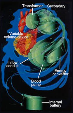
LVAS components include an externally worn battery pack, skin transformer, internal battery, variable-volume device, and integrated electrohydraulic energy convertor/blood pump, Figure 2. The external battery pack contains 12-V dc nickel-cadmium cells that can supply power for up to 10 hr to the pumping system. An inverter changes the external batteries’ dc into ac. The ac flows into a transformer with external primary windings and secondary windings just beneath the skin.
From the skin transformer, the ac is directed to a rectifier, which converts the ac back into dc. The rectifier provides power for the system, or it can recharge an internal nickel-cadmium battery. This battery can power the LVAS for more than 1000 half-hour cycles to allow brief, totally untethered periods of operation.
Finally, power reaches the energy converter/blood pump combination, which is located in a space made available by removing a portion of one of the patient’s ribs. The energy converter case is a biologically inert, investment-cast titanium housing that resists corrosion in a body fluid environment.
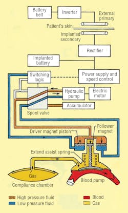
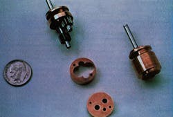
The electrohydraulic energy converter itself, Figure 3, is driven by a 3-phase, permanent-magnet ac synchronous motor. Flow rate of the hydraulics is controlled electronically by varying motor speed. An inverter changes the dc back to ac and controls motor speed by varying ac frequency. Flow direction is governed by hydraulic logic: a 2-way spool valve, check and diaphragm valves, hydraulic switch, and an accumulator.
Hydraulic fluid floods rotating components of the pump-motor to provide cooling and hydrodynamic support of its bearings by eliminating rubbing contact and wear. Heat is dissipated by directing fluid to the outer surface of the energy converter, which lies just under the skin between two ribs. Because it is cooler than the body’s interior, skin acts as a heat sink to carry heat away from the energy converter. Such strategic placement also provides access to interior components of the energy converter without major surgery.
The piston of the energy converter’s double-acting cylinder is magnetically coupled to the blood pump. The magnetic coupling allows hermetically sealing the hydraulic system from the blood pump and offers advantages over a metal bellows seal. A compression spring contributes force to the piston’s thrust by storing energy when the blood pump fills and releasing the stored energy when the blood pump ejects.
The hydraulic system
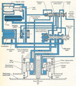
Control of the hydraulic system is simple and reliable. It does not require the transducers or signal-processing circuitry associated with other designs that rely on electrocardiogram (ECG) signals, pusher plate position transducers, and pressure transducers. A tiny gear pump, Figure 4, operates between 5000 and 10,000 rpm, generating flows of 0.5 to 1.0 in.3/sec. System pressures range from 20 to 100 psi, based on the patient’s aortic blood pressure between 70- and 200-mm Hg.
Pressure fluid is alternately supplied above the driver magnet piston to extend the actuator for blood pump ejection. Conversely, fluid is directed below the piston to retract the actuator for pump filling. When in the ejection position (as illustrated), the main spool is held in place by a spring located at the left of the spool. While in this position, the upper actuator volume is ported to pump discharge; the bottom volume is coupled to pump suction.
When the piston approaches its end-of-extension (EOE) limit, pilot pressure at the left of the displacer piston is blocked, shifting the EOE spool valve to the left. This action sends pressure fluid to the left side of the main spool, which overcomes spring force and shifts to the left. Pressure fluid now is routed to the volume below the piston. But this pressure alone is not enough to initiate blood pump filling; it just counterbalances the main spring force. The pump holds this condition until the patient’s left ventricle contracts.
Blood pressure from ventricle contraction combines with the actuator pressure to supply the force necessary to fill the blood pump. The filling process continues until the natural heart has ejected its entire volume or until the piston uncovers the end-of-fill port. If the port is exposed to pressure fluid, the shuttle valve directs this pressure fluid to the right end of the EOE spool. The EOE spool then shifts
to the left and directs flow to shift the main spool back to the extend position. If the piston stops moving prior to uncovering the port, an abrupt reduction in pressure above the piston takes place.
This event produces a piloting action that shifts the main spool back to the right. With the main spool shifted to the right, the actuator extends to cause the blood pump to eject the volume of blood acquired during filling. Blood pump volume and flow rate are controlled by the rate and volume pumped from the heart; maximum stroke volume is 90 cm3 .
This balanced-force sensing approach provides reliable synchronous counter pulsation with no dependence on ECG signals, pusher plate position sensing, or complex electronic signal processing hardware. The end effect of this control scheme is up to a 90% reduction in the natural left ventricle workload.
Support components
The accumulator in Figure 3 serves as a pressure regulator during actuator retraction and as a relief valve at the end of the actuator’s retract stroke. Without the accumulator, slight delays between the end of pump extension and the beginning of left ventricle contraction would cause a pressure increase. This would require large motor controller corrections to maintain optimum torque angle. Wide swings in motor speed would lead to less efficient operation.
Perhaps more importantly, the accumulator stores pressure fluid when the actuator is retracting. This pressure fluid then becomes available during the next heart contraction – an energy-efficient practice that recovers fluid power that would otherwise be wasted.
Fill characteristics of the blood pump are established by the actuator main spring. These characteristics are selected so that the pusher plate begins to retract when blood pressure reaches 2 mm Hg. Blood pressure of at least 15 mm Hg is needed to fully retract the pusher plate. Blood flow from the heart dictates fill time because sufficient hydraulic flow exists to accommodate heart ejection rate with only modest increases in blood pump pressure.
The filter, placed in series with pump discharge flow, traps any particulate contamination circulating in the hydraulic fluid. This is a precautionary device intended to protect the hydraulic system from contamination that might be inadvertently introduced during fabrication, assembly, of testing of the energy converter.
The variable-volume device is an elastomeric diaphragm attached to a rigid backplate. This flexible chamber is attached to the blood pump via a flexible stainless steel duct. Functionally, the device accommodates air displaced by the moving blood pump pusher plate by accepting air during pump filling and allowing it to return during pump ejection.
Electrohydraulic LVASs of this type have been tested in calves for durations of up to 196 days. The systems have been able to synchronize with the left ventricle at over 150 beats per minute and to pump blood at flows exceeding 12 1/min. Two years of multiple-system bench tests and multiple-animal implants of five months are being planned as a precursor to human use.
Hydraulic fluid selection
Initially, silicone oil was selected as fluid for the LVAS’s electrohydraulic energy converter. Selection was based on:
• the ability to tailor the fluid viscosity by blending
• low toxicity
• compatibility with system elastomers, and
• expected resistance to thermal decomposition.
Although satisfactory for nominal operating conditions, resistance to thermal decomposition proved inadequate when gear pump hydrodynamic bearing loads increased when pumping against aortic pressure as high as 200 mm Hg. Because these pressures can occur transiently, alternative fluids with greater thermal stability were evaluated.
Saturated hydrocarbons, which have excellent thermal stability and reasonable lubricity, were investigated, based on discussions with the USAF’s Wright Air Development Center’s Fuels and Lubricants Branch. Pentadecane (C15H32) has the required viscosity of 2.0 cP at the hydraulic fluid operating temperature. The fluid also demonstrated good compatibility with the materials it contacts within the energy converter. Gear pump testing under severe conditions (pressures of 100 psi) showed no tendency toward thermal decomposition. Pentadecane has been substituted for silicone oil in prototype energy converters and endurance units with expected performance as a result.
Richard R. Navarro previously held the position of Senior Research Engineer, Artificial Organs, at Cleveland Clinic Foundation and is currently President and CEO of OrthoData Inc, located in Hinckley, OH. For more information on OrthoData Inc., visit www.orthodatainc.com.
This article was originally published in the June 1996 issue of Hydraulics & Pneumatics. It is reproduced here for its historical value.
