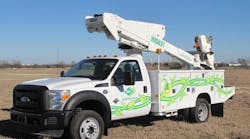
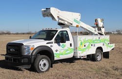
Utility workers use aerial bucket lifts to install and maintain transmission lines and equipment for lighting, traffic control, telephone, and cable services. These lifts are extended and positioned by hydraulic cylinders that are powered by pumps driven by the vehicle’s engine through a power takeoff or clutch pump system. Although bucket lifts that use this conventional approach are effective for operations such as tree trimming, which require frequent motion, a utility technician may stay aloft in one location for long periods without a need to move the bucket as often. Idling the truck’s engine during these periods of inactivity wastes fuel and creates unnecessary pollution.
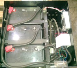
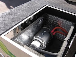
A new Versalift, built by Time Mfg. Co., Waco, Texas, addresses this problem by driving its hydraulic pump with an electric motor that receives power from separate onboard batteries. The self-contained electrohydraulic package itself operates the vehicle’s aerial lift with high efficiency, but the fuel savings from not running the vehicle’s engine can be staggering. The powerful system operates bucket, tools, and outriggers at normal speeds and provides full flow for hydraulic circuit operation of tools. Depending on the battery system and charging method, run times of 40 to 60 minutes are typical between charge cycles. This is sufficient for most operations because the batteries are recharged by the vehicle’s alternator while driving to another location. When equipped with an optional auto-start module, the vehicle will turn on and off automatically to charge the batteries when necessary.
This file type includes high resolution graphics and schematics when applicable.
How it Works
At the jobsite, the operator turns off the chassis engine, sets the parking brake, and turns on the aerial master control switch to ready the aerial lift for work. When the operator activates the controls, a series of on-demand switches located on various hydraulic valves activate the motor/pump.
The electric drives on the electrohydraulic Versalift models are available with three different voltages to meet a range of lift hydraulic requirements. A 12-V system uses two 12-V absorbed glass mat batteries wired in parallel and a 12-V dc motor to provide 2 gpm @ 2000 to 2500 psi. A 36-V system uses three of the batteries wired in series and a 36-Vdc motor to provide 3 gpm @ 2250 psi for the lift or 5 gpm @ 2000 psi for hydraulic tools. A 48-V system uses four of the batteries wired in series and a 48V DC motor to provide 6 gpm @ 3000 psi. All systems use a high-efficiency hydraulic pump, and all batteries are sealed and maintenance-free. (For another type of hydraulic motor solution, check out "Hydraulic Traction Circuit Treats Golf Course Greens Gently.")
The chassis alternator is the primary charging source for the 12-V system — through a battery separator/isolator — with optional (110/220 Vac input) shore power charging available. Shore power (recharging from an ac power line) is the primary charging source for the 36-V and 48-V systems, with an optional converter available to allow charging from the chassis alternator. The system operates on-demand so the 40 to 45 minutes of actual run time available from the battery system typically is twice what a normal daily operation would be. Shore power is used for charging at the end of the day, usually when the vehicle is back at the garage. Run time can be affected by the age of the batteries, environmental conditions, and duty cycle.
Approximate run times are as follows, based on a 70° F temperature and a fully charged system:
12-V System: 2 gpm @ 2000 psi max: 60 minutes of movement
36-V System: 3 gpm @ 2250 psi max: 45 minutes of movement
48-V System: 6 gpm @ 3000 psi max: 40 minutes of movement
Models and Options Meet Market Needs
The electric drive systems are available in many Versalift models, each with some choices between insulated and non-insulated booms and end-mounted or side-mounted boom configurations. Maximum working height varies from approximately 34 to 58 ft, depending on the model. Several other options provide added flexibility for specific application requirements.
Nine standard models are available in combinations that are insulated or non-insulated, end mounted, and with hydraulic controls. The insulated models feature Time Manufacturing’s patented Electroguard design that provides a 42-in. insulation gap in the fully retracted position. The SST-37/40, all VST models, and T-30/34 are available with hydraulic tools at the platform.
This file type includes high resolution graphics and schematics when applicable.
An optional auto-start module will start the chassis engine automatically when either the electric drive or chassis battery becomes depleted. It is used in conjunction with an optional secondary hydraulic source or a dc/dc converter with 36-V and 48-V systems. The dc/dc converter is used when the engine is running to boost the incoming 12-V chassis battery voltage to the 36-V or 48-V output needed to charge the electric drive batteries. The secondary hydraulic source can be added with a traditional power takeoff or clutch pump to allow for situations where the run time of the electric drive is exceeded or for high-demand events. For all electric drive systems, a gauge shows the energy available in the electric drive battery.
Ray Scroggins is a technical writer and president/owner of Scroggins Associates. Contact him at (920) 261-7968, or email [email protected].
