This file type includes high resolution graphics and schematics when applicable.
Electrical motors, generators, and alternators make use of Faraday’s law of electromagnetic induction and its speed requirement. Hydraulic power converters, on the other hand, exploit Pascal’s law and the mechanical advantage that comes from the use of differential areas to either multiply force or multiply speeds.
Hydraulic fluid power, i.e., the transmission via hydraulic fluid, is based on the principle of positive displacement. The laws of energy conservation prevent any hydraulic power-converting machine from multiplying both force and speed at the same time without having more power added into the process.
Pascal’s law states that in a closed container without flow, pressure is transmitted in all directions, undiminished, barring changes in elevation. Changes in elevation can be a problem in some high-pressure hydraulic systems, but is usually negligible. The exceptions to this practice usually apply to the pump inlet portions of their circuits.
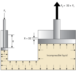
In Figure 1, two different diameter pistons (area ratio is 32 to 1) can multiply the force when the inputs are F1 and X, and the outputs are F2 and an attenuated displacement of only X/32. That is, the pressure is created by the exertion of F1 on the smaller piston, and that pressure, in turn, transmits in all directions throughout the incompressible liquid. It also acts on the bottom of the larger piston and will generate a substantially larger force (F2), which is 32 times larger than the input force (F1).
From a mathematical perspective, since energy must be conserved and the fluid is incompressible, any fluid displaced by the small piston must be absorbed by the movement of the large piston:
F1X1 = F2X2 (1)
The incompressibility of the fluid also requires that volume must be conserved, thus:
X1A1 = X2A2 (2)
This equation is in fact a statement of the positive displacement principle. That is, the fluid displaced by one piston must move something, namely the other piston, to conserve volume.
Rearranging Equations 1 and 2 and substituting yields:
F1 / F2 = X2 / X1 = A1 / A2 (3)
With incompressible fluid, no energy is stored in the fluid, so it follows from Equation 1 that the input power has to equal the output power. Therefore, by dividing both sides of that equation by an arbitrary time to get the velocity:
F1V1 = F2A2 (4)
where V1 and V2 are the velocities of piston 1 and piston 2, respectively.
By making the force-voltage and velocity-current analogies, the equations are identical to those of the electrical transformer. The analogy applies further in noting that the piston area ratio is perfectly analogous to the turns ratio in the transformer. The analogy fails only when comparing the applications. The electrical transformer will work only on ac voltages; however, the dual-piston system in Figure 1 works quite well using dc force and velocity.
But now, the idea of Pascal’s law and the conservation of energy show the fundamental principles of hydraulic incompressible fluid power. The positive displacement principle is also seen in the figure and its analysis.
It is worth noting, at the possible expense of being redundant, that hydraulic fluid is compressible, although by a relatively small amount. For many steady-state calculations, perfect incompressibility is assumed, usually with insignificant error. Incompressibility is measured by the fluid’s bulk modulus. For mineral-based hydraulic oils, that value is about 200,000 psi, which leads to the rule of thumb that fluid compresses about 0.5% per 1,000 psi.
A Simple, but Practical, Pump
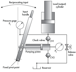
Figure 2 shows a check-valve piston pump that uses reciprocating, mechanical input to move the pumping piston. Two check valves prevent flow in the reverse direction (the official ISO term is non-return valve) when the pumping piston is being withdrawn. This keeps the load cylinder advancing upward with each succeeding stroke of the pump, and locks it into position when pumping stops. A release valve allows the load on the output cylinder to push fluid down and back into the reservoir while simultaneously letting the load descend gradually.
The reciprocating input in this kind of pump is usually done manually by a human. As the input handle is, say, moved to the left, a partial vacuum is created inside the cylinder where the piston is being withdrawn from the bore. That is, the volume increases on the blank side of the piston. Atmospheric pressure acting on the surface of the fluid in the reservoir, being higher than the partial vacuum in the expanding pumping chamber, pushes fluid out of the reservoir and into the expanding volume. This is the filling portion of the pumping cycle.
At some point, the leftward handle movement stops and motion reverses to force the piston back into the pumping chamber. This causes a slight increase in that chamber’s pressure, which forces check valve CV2 into its seat and, in turn, blocks flow from returning to the reservoir, also called the tank. As rightward travel continues, the pumping chamber’s internal pressure increases further.
Assuming the human operator is strong enough, eventually the pressure reaches a level where it equals and just exceeds the pressure induced in the output cylinder, which is caused by some external load (not shown in Figure 2). When the load-induced pressure is exceeded by the pumping piston and the operator, check-valve CV1 lifts off its seat and conducts fluid into the load cylinder. Positive displacement ensures that any further movement of the input handle displaces fluid and forces the load piston and its load to move upward.
Continued reciprocating input will result in progressive rising of the load. To return the load piston to its fully retracted position, the release valve, a device similar to an old-fashioned, screw-type kitchen or bathroom faucet, must be opened. This allows fluid to be pushed back to the reservoir by the output load. It should be apparent that if the release valve opens too far, the load will drop too rapidly. Some appropriate amount of restriction is desirable.
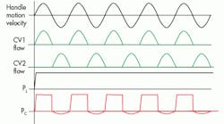
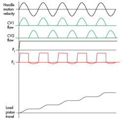
The wave shapes in Figure 3 are approximations that can be expected when a human operator or some other mechanism moves the input handle in sinusoidal manner. An assumption is made that before any motion of either the input handle or the output cylinder and its load occurs, the output piston is resting at its fully retracted position. Thus, the weight of the external load (shown in Figure 3 only as an arrow) is carried by the stationary parts of the cylinder, which means there’s no pressure in the load cylinder blank end. Additionally, the release valve is assumed to be closed (shut off), preventing any fluid from the load pressure region of the piston from leaking back to the reservoir.
Given those conditions, and that the handle is at its most leftward position, the input motion begins its sinusoidal velocity. Being a sinusoidal input motion, the output flow is likewise a sinusoid, at least during the first half of the input cycle. It is labeled as CV1 flow.
The load pressure, as already stated, starts at 0.0 and any small motion of the pumping piston causes the pressure in the pumping cavity to rise very sharply, which opens CV1. As soon as the piston moves some tiny amount, the load pressure (PL) is determined primarily by the external load because the pressure in the blank end of the cylinder carries the load. The piston will have been lifted off its mechanical resting place at the bottom of its travel.
Meanwhile, the pressure in the blank end of the pumping piston (PC) has an almost square shape due to the incompressible nature of the fluid. And small piston movement causes the pressure to rise until CV1 opens and the pressure is determined by the external load. This results in a nearly flat top for all practical purposes.
As soon as the pumping piston stops moving, a precipitous drop occurs in the pumping chamber pressure, causing it to drop to zero. When the motion is reversed, the pressure in the blank end actually drops below zero, creating a partial vacuum. As a result, the external atmospheric pressure acts on the reservoir surface to push fluid into the expanding chamber.
As the input motion proceeds, each forward stroke of the handle results in the load piston rising by an amount determined by the amount of volume displaced by the pumping piston and the area of the load piston. Continued pumping-handle input motion results in the steady rise of the load, but interspersed with pauses while the reversed input action allows the ejected fluid to be replenished on the fill portion of the cycle.
When the input motion stops, the load piston is held in its last position because the fluid trapped in the load cylinder’s blank end cannot escape. To lower the load, the release valve must be opened, which enables the trapped and pressurized fluid to be flushed back to the reservoir, motivated by the heavy external load.
A Double-Acting Variation
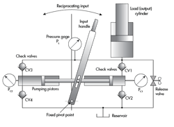
A second piston can be easily added to the manually operated piston pump (Fig. 2, again), making it into a so-called double-acting piston pump (Fig. 4). In other words, it will expel fluid from the pumping pistons into the load cylinder during each half cycle.
Practitioners of the electronic arts will recognize immediately that the four check valves form a full-wave rectifier bridge. The bridge converts the reciprocating flow in each of the two pumping pistons into unidirectional (dc) flow in the load cylinder, albeit pulsating with each input half-cycle. When the handle moves to the right, CV1 opens, allowing displaced, pressurized fluid to be expelled into the load. During that same rightward motion, CV4 opens, due to the partial vacuum created by the expanding cylinder chamber, filling the left-side cylinder with unpressurized fluid. And so the cycle continues as input handle motion.
Astute observers will also realize that in pumps, as well as generators, the outside world may exhibit unidirectional flow and direct current. However, within the innards of the machines, both electrical and hydraulic, it is an ac world.
