This file type includes high-resolution graphics and schematics when applicable.
Continuing the discussion from the last installment of “Motion Control,” internal leakage is not the only loss in the pump. There are technical frictional losses as well. These are symbolized algebraically with Rfw, meaning “friction and windage,” an ages-old term for the analogous frictional losses in electrical motors and generators.
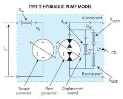
In summary, Fig. 3 consists of two ideal elements: one for the torque generator on the input (mechanical) side and the ideal pumping element on the hydraulic side. The Morse-code outline shows the boundaries of the pump and represents the case of the pump housing that captures internal leakage. Three parasitic resistance loss coefficients account for the three distinct internal leakage paths, and the pump of Fig. 3 is equipped with a case drain.
However, some explanation is needed regarding the two small, white-filled triangles in the vicinity of the pump’s case-drain port. One indicates fluid carried away from the common node between RLACD and RLBCD and into the pump’s housing. Some pressure builds, and when an external path is provided at the case-drain port, the component of internal leakage flows back to the tank.
If the case-drain port is blocked, the case internal pressure will rise. It may reach 50% of the outlet pressure, because the only relief is through the restriction at RLBCD. The high case pressure will demand a sturdy pump housing and a high-pressure shaft seal.
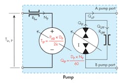
If the case-drain port is blocked, or if it doesn’t exist, then all of the previously mentioned limitations exist. More importantly, though, the three separate internal leakage resistances will combine to form a new, single, port-to-port leakage resistance in schematic form. The new, simplified analytical schematic is shown in Fig. 5.
Hydraulic Motors
The reality is that hydraulic pumps and motors are essentially the same machines, especially in the hydrostatic transmission. In some applications, the pump and motor are forever exchanging roles. When accelerating, a pump is a pump and a motor is a motor. But when decelerating (especially if the loads have significant inertia), the motor absorbs mechanical energy from that stored in the spinning inertia, which is transmitted to the pump as hydraulic energy, turning the pump into a motor.
chanical power that comes out of the pump shaft is transmitted mechanically to the prime mover. If the prime mover is an electric motor, it converts the mechanical power into electrical power and transfers it to the power grid to be used elsewhere. This is an example of an efficient, fully energy-regenerative system. More will be discussed later about this phenomenon in the next installment of “Motion Control.”
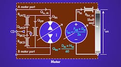
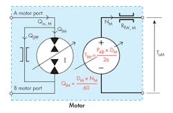
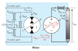
For now, it should be apparent that the similarity between a pump and a motor should result in analytical schematics that are similar. Indeed, that is exactly the case. The analytical schematic is essentially the mirror image of the pump. Figures 4 and 6 are the analytical schematics for Type-1 and Type-2 hydraulic motors. They should be compared to Figures 3 and 5. The significant difference between a pump and a motor is the direction of energy flow.
An important aim of this discussion is to show how the ideal pump and motor serve as a basis for depicting and explaining hydromechanical energy conversion, as well as providing the fundamental principles of that energetic process. Plus, it is a relatively simple matter to add the energy-loss elements of fluid friction (internal leakage paths, created by necessary clearances and a provider of internal lubrication) and mechanical friction (unavoidable in the real world) to create a schematic representation of more practical machines that have less than 100% efficiency. The analytical schematics account for these losses; they also show how the leakage paths exist within the machine and how they must be treated to make the machine free of external leakage.
A hydraulic machine, say a motor, works like this: If a flow source is connected to the motor, the immediate reaction is that the pressure rises because the motor is not moving. However, in a few milliseconds, it rises enough to overcome the friction, and the motor and its load accelerate. Speed continues to increase until all of the flow goes into the motor’s internal displacement chambers, at which time the motor has reached its steady-state speed. That is, the pump output flow and the motor input flow are balanced and equal.
The motor’s speed is controlled by the output flow from the pump. If pump flow increases due to greater displacement or input speed, the pump output flow increases, and the motor will accelerate. This is one of the most fundamental principles of hydraulic machines. Moreover, in every pump there’s a motor, and in every motor there’s a pump.
