This file type includes high resolution graphics and schematics when applicapable.
Because all hydraulic and pneumatic systems should contain a relief, they can undergo blowdown. Blowdown typically results from friction or other energy losses due to change in a process operation’s sense of direction (reversal). Its mechanical analog is deadband or backlash, and an electrical equivalent resembles hysteresis.
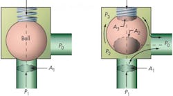
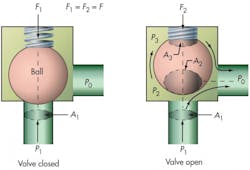
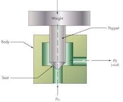
Imagine a simple ball type relief valve as shown in Figure 1. The system pressure to be controlled is p1 acting on A1. When the ball lifts at the set pressure, fluid is dumped downstream to tank at a certain backpressure p0. The term backpressure only refers to the downstream pressure at the outlet of the valve.
For the valve shown in Figure 1, fluid flow occurs across the seat area A1 (an orifice) and is driven by the pressure difference between p1 and p0. Normally, this backpressure eventually leads to a sump at atmospheric pressure, such as a reservoir. Sometimes, however, the diameter of downstream tube, pipe, or hose is not large enough to handle the flow, so the backpressure applied to the valve seat rises.
Alternatively, if substantial static pressure exists in the reservoir fluid at the end of the return line (as in a pressurized reservoir or one that is extremely deep), p0 will exceed atmospheric pressure. This can cause excessive backpressure, thereby reducing return flow. The higher static downstream pressure changes the force balance in the valve, affecting the set point of the valve.
Blowdown, however, refers only to the system pressure, p1. When the system pressure rises to exceed the set point, the valve opens, and flow commences. However, the valve will not reseat when system pressure drops back down to the set point. Instead, system pressure continues to fall. The valve will close when conditions are correct, but at a lower value than the opening (set) pressure. The difference in pressure between the set point and the final closing point is called the blowdown pressure drop, and it is usually specified as a percent of the set pressure.
A certain amount of blowdown is desirable to prevent limit cycle oscillations. Excessive blowdown, though, usually leads to reduced system performance. Within fluid systems, two effects primarily cause blowdown:
- Geometry change in the relief valve as it opens and closes, presenting a variation in pressure-sensitive valve areas.
- Redistribution of internal pressures on the working, sensitive (operational) valve areas. This often occurs when flow within the valve relieves the overpressure during the open part of the relief process.
Limit Cycles
Nonetheless, a certain amount of blowdown is desirable as a stabilizing mechanism. Suppose a valve is set for 1,000 psi in a system with rising pressure. When the pressure rises to 1,000 psi, the valve opens and triggers relief flow. It’s possibly due to system mass and inertia that some system overpressure occurs before the flow begins to relieve the system. The poppet remains in the open position and, subsequently, the relief flow begins to correct the pressure by dropping it.
In this case, we assume a “perfect” valve that does not exhibit blowdown. When system pressure drops to the set point of 1,000 psi, the valve slams shut. The entire leg of moving fluid suddenly stops and the kinetic energy transforms to a pressure rise. Water hammer ensues, and the valve encounters more than the 1,000-psi set pressure. This causes the poppet to lift, which allows relief flow to proceed again. The flow relieves the pressure and the valve poppet shuts again, producing another cycle of water hammer. This process can repeat, causing limit-cycle chatter. Ultimately, such a “hammering cycle” can destroy the valves. If mechanical resonance occurs within the valve, it may couple with the limit cycle and cause fatal results. Some relief valves are designed with fluid-damping chambers to dissipate energy and prevent further harm.
A different scenario arises with a “less-than-perfect” valve that exhibits blowdown. For example, the valve opens at 1,000 psi, and after a short time, the pressure begins dropping below 1,000 psi into the blowdown zone. At 800 psi, the valve finally slams shut, stopping the relief flow. This transforms the kinetic energy to a momentary pressure rise, say 950 psi. The 1,000-psi valve set point, however, keeps the valve shut. In this case, blowdown was a benefit because it prevented limit-cycle chatter.
Causes Of Blowdown
As discussed, blowdown in relief valves arises from a geometric change, as seen by the fluid. It’s induced by the moving part(s) internal to the valve, and/or changes in pressure distribution on these moving internal parts during the relief-flow phase.
Digging deeper into these causes, consider the simplest form of relief valve typical of fluid systems — a valve utilizing a spring-loaded ball, Figure 1. When the valve is closed, the poppet (ball) experiences a net seating force, where p1A1 < F, Figure 1a.
Here, the system pressure, p1, acting over the seat area, A1, is less than the spring force, F. When p1 exceeds the set value, Figure 1b, the force balance shifts and p1A1 exceeds F. This lifts the ball off the seat, permitting flow to the reservoir, which is at p0. Notice that the ball sees a totally different pressure distribution due to the flow as it passes around it: some pressure is applied locally around the seat area; some pressure (p2) is applied over a greater area (A2) around the sides of the ball near the bottom; and some pressure (p3) is applied to an area A3 in the spring zone at the top of the ball. Although the relief flow ultimately occurs between p1 and p0, intermediate paths sustain pressure drops so that p1 > p2 > p3 > p0. This variation is due to intermediate valve geometry, essentially a series of orifices that the flow must pass through. The area of these orifices is related to the geometry, Figure 2. In this example, O1 is the equivalent orifice at the inlet seat; O2 is the equivalent orifice for flow past the bottom of the ball; O3 is the equivalent orifice for some flow past the top of the ball; and O4 is the equivalent orifice for the final relief flow into the sump.
The exact modeling of these orifices can be quite a difficult task, because the valve’s dynamics may vary considerably. Therefore, the above orifice concept must only be regarded qualitatively as a method to help explain blowdown.
Using the orifice concept to determine the pressure distributions on areas A1, A2, and A3 (Figure 1b, again) is a complex task beyond the scope of this article. However, for simplicity, the following general relations hold:
When p1 < pset, then F >p1A1 with the valve closed.
When p1 = pset, then F = p1A1 with the valve about to open.
After p1 > pset, flow commences, and pressures in the valve adjust so that:
F + p3A3 = p1A1 + p2A2
Note that as the spring lifts, spring force rises slightly due to the spring rate (F2 > F1). The discrete pressures and areas were arbitrarily assigned to simplify explanation of the action of flow on the valve’s internal components. In actuality, discrete pressures at specific locations as shown might apply differently.
For example, pressures might vary from one vertical location on the ball to another as a function of the ball’s vertical movement. p1 and A1 are the pressures and areas that interact at the various vertical ball positions to define the force balance during flows. Using these notations, the generalized force balance along the poppet motion direction becomes the vectoral summation of all the individual pressures and areas. Note that pressures act normal to the areas. Actual performance of this task is complex and beyond the scope of this discussion.
Single-Stage Valve Example
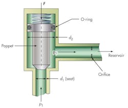
Consider Figure 3, a simple direct operating single-stage valve. The system pressure is seen as p1 applied over the port seat diameter, d1. The poppet is loaded by spring force, F. The valve will begin to open when F1 = p1A1. Flow then passes through the long relief pipe to the reservoir at pressure p0. The pipe’s length exhibits a resistance to flow, so a pressure drop occurs along this path. This is represented schematically as an orifice. Thus, it’s assumed that the poppet is completely open (and shows little resistance to flow) during relief flow, and the entire internal portion of the valve between the seat and the orifice is at system pressure.
Note that the upper body of the poppet is larger than the seat diameter, d2, which sees a pressure of p1. The upward force balance on the poppet is p1A2. So, for this example:
A2 = π(d22)/4.
An additional lift force now exists on the poppet, and it will not reseat until p1 drops below the original set pressure. Assuming that the spring force remains constant during the flow period, the reseat pressure is:
p1 (reseat) = p1 (set) × (d1/d2)2.
Because d1/d2 is carried as a square ratio, the reseat pressure can be quite low with a significant loss of system pressure. For example, if the poppet diameter, d2, is 0.5 in., and the seat diameter is 0.25 in. — a ratio of 2:1 — blowdown is 75%, which is excessive. In this simple case, two solutions are possible: shorten the relief pipe so that the valve internals see p0 during flow; or remove the poppet’s O-ring so that the additional area due to d2 will be partially balanced in the spring zone. The latter solution may result in limit-cycle chatter.
Inverted Pilot-Operated Valve Example
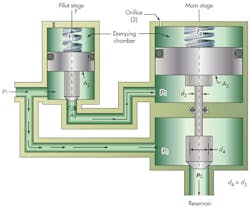
Figure 4 shows an inverted pilot-operated valve designed for large flows. Both the pilot and main poppets are exposed to system pressure. Spring force keeps the pilot poppet on the seat. When system pressure rises, the pilot poppet lifts and exposes the main poppet’s actuator A3 to p1 at the set point. In the main section, stem diameter d3 is much less than seat diameter d4. Such a design increases the seating force in parallel with rising system pressure. Therefore, the seat sealing force remains high until the pilot valve causes the main poppet to lift.
When the pilot opens and fluid flows into the main actuator region, exposing it to system pressure, the actuator area exceeds the main seat area. In addition, the net force against the spring lifts the main poppet. The pilot closes upon restoration of set pressure force balance, which then closes the main section (a small orifice aids the closing motion by bleeding the spring zone, which also acts as a damping chamber).
When the pilot opens and allows flows, it fills the zone under the main actuator and lifts the main poppet. After the lift is complete, the fluid leg between the pilot seat and the actuator becomes a dead leg. The pressure throughout this zone now sits at p1. Therefore, internal components of the pilot see system pressure. The pilot’s force balance, caused by the ratio of areas A1/A2, now changes from the preflow conditions to affect the closing pressure. Here, the pilot closing pressure is lower than its opening pressure.
The force balances at the pilot on opening are: F1o + p1oA1 = p1oA2;
On closing they are: F1c = p1cA2.
Because spring force in the pilot remains nearly constant: F1o = F1c
Also, the closing pressure existing in the pilot is: p1c = p1o (A2A1)/A2 = p1o [1 ‒ (d1/d2)2].
The blowdown strongly relates to the squares of the poppet dimensions, as in the previous example.
A brief history on relief valves
The relief valve was reported to have been used (or perhaps invented by) James Watt to prevent boiler explosions in his early pressure-driven steam engines used for driving locomotives. The original valves were placed close to the engineer’s cabin where the fireman would shovel coal to feed the fire. Early engines had no sophisticated feedback systems to regulate boiler pressure except the relief valve. When the boiler pressure would reach (or exceed) the valve’s set pressure (say 50 psi), it would open and blow off.
Bob Archer is a consulting mechanical engineer in Woodbury, N. Y. For more information, contact him at [email protected].
