Hydraulicspneumatics 776 Clown Pole

Troubleshooting Challenge: Locking valves cause pole in circus act to drift

April 11, 2013
In the latest Troubleshooting Challenge, Robert Sheaf poses a question as to why locking valves that control a hydraulic cylinder are drifting in a circus clown act.
During a circus act, a clown balances on a platform resting on the end of a 60-ft pole. The platform has a double rail on all four sides, and the top rail is about waist high. The clown acts like he is trying to cause the pole to sway back and forth, which causes it to break loose and drop to about 30 ft above an open cage holding tigers and lions. The clown falls through
the railing and bounces up and down on a bungee cord just above the animals. The pole then starts to slowly drop another 10 ft, almost to the point where the big cats can get him. The pole should stop at that point, when blocking valves are de-energized to prevent further movement.

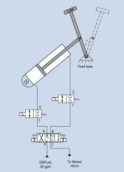
The pole is hydraulically driven by a cylinder hidden under a false wood shed. The cylinder has a blocking valve on each of its ports and is driven with a proportional valve, as seen in the circuit.

When the pole stops the first time, the locking valves stop all movement. When the proportional valve stops it again after the 10 ft of slow movement, the locking valves should engage and stop all movement. However, the pole continues to drift down slowly until the cylinder bottoms out extending.

The cylinder was inspected and deemed to be in like-new shape as were the locking valves. So why does the pole drift in slow mode but not when it is stopped in fast mode?

Robert J. Sheaf Jr., is founder and president of CFC Industrial Training, a Div. of CFC Solar, which provides technical training, consulting, and field services to any industry using fluid power technology. Visit www.cfc-solar.com for more information.

Solution to problem

On the circus act where the clown rode the top of a 60 ft pole that drifted after the slow mode was told to stop, the locking valves were causing the problem. The circuit symbol shown in the schematic showed a spring returning the valve to the closed-and-locked position and a solenoid would force it open. The valves were rated for a 30 gpm flow at a 140 psi pressure drop.
The valve manufacturer's catalog described the valve as “internally piloted, bi-directional, load-holding valve with 7 drops per minute maximum leakage at 3500 psi.” What the catalog did not say was that it required a 30 to 40 psi pressure drop across the valve to provide sufficient pilot pressure to ensure the valve would close completely. The valve also had a preferred flow path.

The manufacturer was consulted and they provided modified valves with stronger springs that did not require any pilot pressure to help shift and hold the valve closed.
Continue Reading

BOOK 2, CHAPTER 12: Fluid Motor Circuits

March 18, 2009
Table of Contents

Motor leakage variations

Oct. 18, 2006
affect low-speed performance

Sponsored Recommendations

All-In-One DC-UPS Power Solutions

March 13, 2024
Introducing the All-In-One DC-UPS, a versatile solution combining multiple functionalities in a single device. Serving as a power supply, battery charger, battery care module,...

Motor Disconnect Switches

March 13, 2024
With experienced Product Engineers and Customer Service personnel, Altech provides solutions to your most pressing application challenges. All with one thought in mind - to ensure...

Industrial Straight-Through Cable Gland

March 13, 2024
Learn more about Altech's cable glands and all they have to offer for your needs!

7 Key Considerations for Selecting a Medical Pump

Feb. 6, 2024
Newcomers to medical device design may think pressure and flow rate are sufficient parameters whenselecting a pump. While this may be true in some industrial applications, medical...