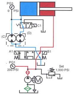
When you must to split a single hydraulic line into two or more identical flow paths, a tee or several tees can be the first solution. However, if the resistance in all the branches is not identical, flow can vary greatly in each path. Adding flow controls at the tee outlets makes it possible to change resistance and equalize flow in each branch, but as the machine operates, work resistance changes often require constant flow modifications. A device called a flow divider splits flow and compensates for pressure differences in most cases. A flow divider can split flow equally, unequally, and into more than two paths. One design maintains a constant flow for one outlet and directs any excess flow to a second outlet.
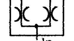
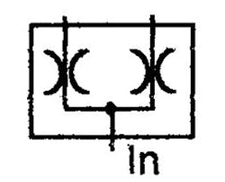
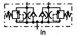
Figure 11-1 pictures the ISO symbol for a flow-dividing valve. While the ISO symbol shows the function of the valve, it does not indicate which design it is. Fluid entering the flow divider splits and passes to both outlets equally. Figure 11-2 shows the symbol for a spool-type flow-divider and gives a better indication of the valve’s operation. Note that a spool-type flow divider will not allow reverse flow. When using a spool-type flow divider to synchronize cylinders, add check valves to pass reverse flow. However, when the cylinders reverse, there is no synchronization with a spool-type flow divider.
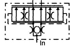
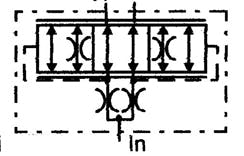
Figure 11-3 shows a divider/combiner that synchronizes actuators in both directions of travel. It splits pump flow to the actuators and also assures that equal reverse flow returns from both cylinder ports.
Figure 11-4 pictures a flow divider with bypass relief valves that allow a lagging cylinder to complete its stroke. Reverse-flow check valves allow free flow around the divider spool while the actuator returns.
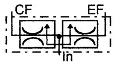
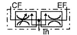
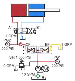
Figures 11-5 and 11-6 show a priority flow-divider symbol. Port CF (controlled flow) of this flow divider always has the same flow when the pump is producing that flow or more. Excess pump flow goes through port EF (excess flow) to tank — or to another circuit.
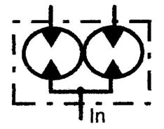
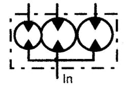
Figures 11-7 and 11-8 show motor-type flow-divider symbols (as drawn by the manufacturers). This type flow divider is more efficient in most circuits. Motor-type flow dividers also work well in flow- and/or pressure-intensification circuits. They are available with multiple outlet ports and/or unequal flows.
Spool-type flow dividers and circuits
Spool-type flow dividers split flow through pressure-compensated fixed orifices. The pressure-compensation feature ensures near-equal flow through the orifices — even when inlet and/or outlet pressures fluctuate.
Spool-type flow dividers can split flow equally or unequally, according to the orifice sizes. Always use spool-type flow dividers at or near their rated flow. Because most designs use fixed orifices, equality of flow is poor when used below their rated flow. If flow exceeds the rating of the valve, high pressure drop causes poor performance and fluid heating.
The dividing accuracy of spool-type flow dividers can be as close as ±5%, depending on the pressure difference at the outlet ports.
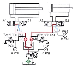
Figure 11-9 shows a spool-type flow divider splitting pump flow equally. With this circuit, flow to each directional valve is nearly equal, even with one cylinder working at high pressure while the other cylinder is at low pressure or stopped by a centered valve.
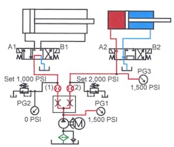
In Figure 11-10, fluid from port 1 flows to tank through the directional valve while fluid from port 2 drives a cylinder. Pressure at port 1 is 0 psi while pressure at port 2 is 1500 psi. Under these conditions, pressure at the flow divider inlet also is 1500 psi. Pressure at the inlet of a spool-type flow divider is always equal to the highest-pressure outlet. This condition generates a lot of heat because pressurized oil leaving port 1 is not doing work. It is best to use a spool-type flow divider in circuits where both outlet ports are at or near the same pressure. The higher the pressure variation, the greater the energy wasted as heat with spool-type flow dividers. When outlet pressures continuously vary by more than 300 to 500 psi, it is best to use a motor-type flow divider.
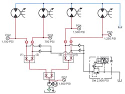
When splitting flow into more than two paths, add another spool-type flow divider to each outlet of the first divider. Figure 11-11 shows a synchronizing circuit for four unidirectional hydraulic motors. Flow split equally by the first spool-type flow divider goes to two more spool-type flow dividers. The second pair of spool-type flow dividers split the half flow from the first spool-type flow divider, and sends equal flow to the four motors.
When using spool-type flow dividers for equal flow, the total number of dividers must be an odd number. If used in any even combination, flow will not be equal from all outlets -- unless the first divider has unequal flow from its outlets.
To get three equal outputs with spool-type flow dividers use one with unequal outputs, say 33.3% and 66.7%. Send flow from the 33.3% side to power the first actuator. Send flow from the 66.7% side to an equal-flow divider. Flows from the equal flow divider outlets is now 33.3% of total pump flow, so all three outputs are the same.
Notice that these circuits cannot handle reverse flow. Reverse flow through a spool-type flow divider will lock up one actuator when return pressure differs at the outlet ports.
Also notice that each outlet of a flow divider can have a different pressure. Figure 11-9 shows outlet 1 with a relief valve set at 1500 psi, and outlet 2 set at 2000 psi. (If both cylinders operate at the same pressure, substitute a single relief valve at the pump.) However, if both cylinders are moving and one of them stalls at 2000 psi, both cylinders will stop. The relief valve arrangement in Figure 11-11 allows any motor needing more than 2000 psi to stop while all other motors continue turning.
Spool-type flow divider/combiners
Spool-type flow dividers only allow flow in one direction. From the symbol in Figure 11-2, it is plain that reverse flow would lock up one of the cylinders. The cylinder that needs less resistance actually gets more. In a circuit where flow must go both ways, use a check valve to bypass the flow divider.
Figure 11-12 shows spool-type flow dividers in a circuit that synchronizes two cylinders. As the cylinders extend, the flow divider splits the flow and cylinder speed is nearly the same. When the cylinders retract, bypass check valves allow fluid to go around the divider. There is no synchronization from the cap-end flow divider at this time. A second flow divider with bypass check valves on the rod-end ports (as shown) is necessary for identical movement while retracting. As depicted in Figure 11-4, some flow dividers come with integral bypass check valves. Integral bypass check valves save piping time, have fewer leaks, and are more compact.
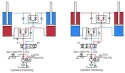
Because flow dividers are not 100% accurate, one of the cylinders may lag. Because there is internal leakage past the spool, any flow divider will let the lagging cylinder continue its travel. Because of the bypass leakage, the speed of the lagging cylinder while it is going to the end of its stroke is very slow. Integral relief valves (as shown in Figure 11-4) allow the lagging cylinder to catch up quickly. Set these relief valves between 50 and 150 psi. Once the pressure difference across the valve reaches this pressure range, fluid bypasses the restricted spool to quickly re-phase the cylinders.
In Figure 11-13, a single flow divider/combiner synchronizes cylinders in both directions of travel. Here a flow divider/combiner replaces the flow divider and check valves in Figure 11-12. Because there is no ANSI symbol for the flow divider/combiner, add bi-directional arrows to the one-way flow-divider symbol. This more-detailed symbol helps to clarify the valve’s action. Bi-directional arrows show the divider/combiner function. These detailed symbols come from manufacturers’ catalogs and represent their interpretation of their valve’s function.
As the cylinders extend, the divider/combiner splits the flow to keep cylinder speeds nearly the same. When the cylinders retract, the divider/combiner shifts internally and equalizes return flow also.
A flow divider/combiner wastes energy the same as a standard flow divider. In essence these devices are infinitely variable pressure-compensated flow control pairs. Any flow control will cause heat because it is a restriction.
Flow dividers or flow divider/combiners are not designed to control running-away loads. For the circuits in Figures 11-12 and 11-13, a counterbalance valve in the line between the directional valve and the flow divider may be necessary if the loads can run away.
Spool-type priority flow dividers
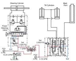
Figure 11-14 shows a typical spool-type priority flow divider circuit. A priority flow divider maintains constant flow from the controlled flow (CF) port. Any additional flow passes out the excess flow (EF) port. The non-standard symbol in the Figure is one typically found in manufacturers’ catalogs. The controlled flow may be fixed or adjustable, according to the circuit needs. The excess flow may be sent to tank or to another circuit as required. (When there is pressure at the excess flow port, make sure the valve design can handle it.)
Some priority flow dividers are more like 3-port flow controls and cannot stand backpressure at the EF port. Use these flow dividers for bleed-off flow controlling only. With a bleed-off type priority flow divider, pressure at EF port causes flow at the CF port to fluctuate.
In Figure 11-14, a fixed-orifice priority flow divider is used on a vehicle with power steering and hydraulic actuators. This is the standard circuit for a forklift truck using a fixed-volume pump. The power-steering circuit needs 7 gpm and pump flow at idle is a minimum of 10 gpm. The actuators need as much as 15 gpm for maximum speed.
When the vehicle is operating, the power steering circuit will always have at least 7 gpm. When the mast or tilt cylinders need fluid, excess pump flow operates them. Because there is little excess flow at idle, the mast and tilt cylinder's speeds are slow at this time.
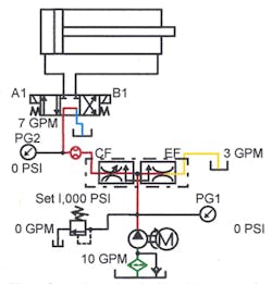
The circuit in Figures 11-15 and 11-16 controls the speed of a hydraulic cylinder powered by a fixed-volume pump. The adjustable controlled-flow port of the priority flow divider connects to the cylinder valve, with the excess-flow port piped to tank. This arrangement controls cylinder speed and keeps heat build up low because the pressure in this circuit is only slightly higher than the cylinder needs.
Most priority flow dividers are pressure compensating so the priority flow remains constant even when pressure changes occur. As long as there is enough pump output, the controlled flow is constant. Excess flow changes as pump volume varies.
A priority flow divider wastes energy just like any spool-type divider. The inlet pressure to the divider is the same as the highest outlet pressure. When either outlet port is pressurized, the port with little or no pressure is wasting energy and generating heat.
Rotary (motor-type) flow dividers and circuits
Rotary (motor-type) flow dividers consist of two or more hydraulic motors in a common housing. All the motors share a common shaft, so they all turn at the same speed. All motors have a common inlet but separate outlets. If the motors have the same displacement, the output from each motor is nearly equal. (Some motor-type flow dividers use motors with different displacements, so each section’s output differs.) The big advantage of a rotary flow divider over a spool-type flow divider is energy transfer between sections. A spool-type flow divider's inlet pressure is always equal to the highest outlet pressure. This means heat generation from the lower or 0 pressure outlets, because pressurized fluid goes to tank without doing any work.
In contrast, a rotary flow divider’s inlet pressure is the average of the sum of the outlet pressures. Because there is a mechanical link between sections, excess energy transfer via this link greatly reduces heat generation. Because hydraulic motors are not 100% efficient, there still is some energy loss and heat generation in any motor-type flow divider.
Another advantage of rotary flow dividers is their outlet options. A spool-type flow divider has only two outlets; a rotary flow divider can have many outlets — in even or odd numbers. Most manufacturers catalog units with 6 to 8 outlets, but also will custom-build dividers to suit.
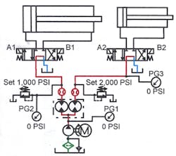
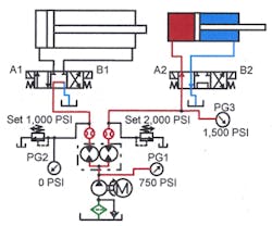
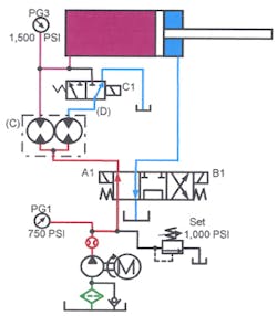
Figure 11-17 shows a rotary flow divider splitting flow from a fixed-volume pump to separate actuators. With the cylinders at rest, all flow goes to tank through the tandem-center valves with minimal energy loss. To stroke the cylinder on the right, shift its directional valve as in Figure 11-18. Flow from the right-hand section of the rotary flow divider sends half of the pump’s flow to the right-hand cylinder at 1500 psi. The other half of the pump’s flow goes to tank through the left valve at 0 pressure. Notice that pump pressure is approximately 750 psi instead of 1500 psi as in Figure 11-10. Pump pressure is low because most of the energy in the flow divider outlet going to tank mechanically transfers from the idling motor to the working motor. Whether one or both cylinders do work, energy going in is always equal to energy needed plus inefficiencies.
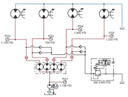
The 4-outlet rotary flow divider in Figure 11-19 supplies four hydraulic motors. Because each motor has a different load, pressure at the motor inlets is not the same. To figure the approximate inlet pressure to the flow divider, add the outlet pressures and divide by the number of outlets. (1100 psi + 700 psi + 1250 psi + 1500 psi = 4550 psi. Divide by four outlets and 1138 psi is the pressure at the pump outlet). The 1138-psi figure is approximate due to losses in piping and the motors of the flow divider.
Notice the relief valve at the flow divider outlets. Because a rotary flow divider also acts as an intensifier (See Figures 11-45 through 11-48), it is necessary to limit the pressure at each outlet. If each motor needs a different pressure, use separate relief valves at each flow divider outlet. In Figure 11-19, a set of check valves and a single relief valve sets the same pressure for each motor — and protects them from overpressure. Because the relief valve is solenoid-operated it also starts and stops all motors simultaneously.
Rotary flow divider synchronizing two cylinders
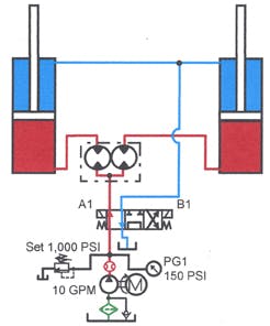
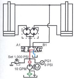
Rotary flow dividers work well for synchronizing actuators. Figure 11-20 shows two cylinders synchronized by a double equal-outlet, rotary flow divider. Install the flow divider between the valve and the cylinder cap-end ports as shown. This arrangement synchronizes the extension stroke of the cylinders and provides some control for the retraction stroke (See Figures 11-22 and 11-23). Use a second flow divider at the rod-end ports for precise control on the retraction stroke when required.
As the cylinders extend, as in Figure 11-21, the flow divider splits pump flow, causing the actuators to extend at the same time. If the cylinders’ loads require different pressures, the flow divider still sends almost equal flow to each port. A rotary flow divider has some internal bypass, causing the section with the higher outlet pressure to pass less than half flow. Therefore, use rotary flow dividers for circuits needing only nominal synchronization. With any type of hydraulically controlled synchronization, always take the cylinders to a fixed position at one or both ends of the stroke.
Also, if pressure intensification above any of the system’s component ratings is possible, put a relief valve at the flow divider outlets. Several manufacturers supply their flow dividers with integral bypass relief valves. Set these relief valves for a safe pressure differential so intensification will not damage the cylinder. When a bypass relief valve starts relieving, the cylinder on that side stops while the opposite cylinder’s speed doubles. (If integral relief valves are not available, install external relief valves when there is a chance for actuator damage from high pressures.)
Some manufacturers pipe the integral relief valve’s outlet to tank instead of back to the flow divider inlet. This type of relief valve circuit dumps fluid to tank at a pressure low enough to keep from damaging the actuator. Using a relief valve with its outlet piped to tank causes one actuator to stop and allows the other one to continue at the same speed.
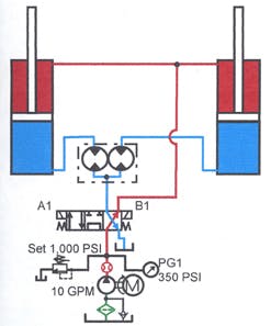
Figure 11-22 shows how the cylinders retract under normal conditions. Flow from the pump goes to both rod-end ports and the cylinders retract together. The flow divider combines the oil from the cap-end ports and synchronization continues. However, if one cylinder binds on the retract stroke, the cylinder with less drag will run away.
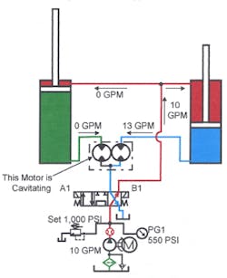
Figure 11-23 depicts what happens when a cylinder binds. All flow from the pump goes to the right-hand cylinder — retracting it at double speed. The right-hand motor of the flow divider turns rapidly due to the high flow. The left-hand motor of the flow divider also turns rapidly, but no oil passes through it. The left-hand motor cavitates due to this lack of fluid. After the right-hand cylinder bottoms out, pressure buildup may cause the left-hand cylinder to retract. As the left-hand cylinder retracts, the right-hand motor of the flow divider cavitates.
If the cylinders in a circuit have different return-force requirements, or are subject to binding, add a second rotary flow divider at the cylinders’ rod-end ports. The second flow divider ensures that the cylinders are synchronized on their retraction strokes also. (See Chapter 22, covering Synchronizing Circuits, for other ways to make actuators move at the same rate.)
Rotary flow divider in a priority circuit
Using a rotary flow divider in a priority circuit like the one shown in Figure 11-16 will give unsatisfactory results. A spool-type priority flow divider sends a constant flow to one outlet as long as the pump produces at least that much flow. When pump flow increases, priority flow stays the same while the other outlet’s flow starts or increases. Flow from the priority outlet stays constant through the entire pump range.
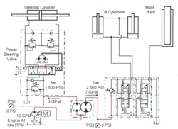
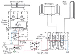
Figures 11-24 and 11-25 show what happens when using a rotary flow divider in place of a spool-type priority flow divider. With the engine at idle speed, 3 gpm flows to the power steering and 7 gpm to the cylinder circuit. This circuit works well at idle — if 3 gpm is enough for the power steering. Figure 11-25 indicates what happens when engine rpm and flow increase. As pump flow increases, both the power steering and the cylinder circuits receive more fluid in the same ratio. This overspeeds the power steering while robbing oil from the cylinder circuit. (There would be little or no heat generation from this circuit, but the end result would be less than satisfactory.) Rotary flow dividers with unequal flow outlets are available in various combinations and multiple flow paths. However, the flow from each outlet changes proportionately as the inlet flow changes. This feature makes them hard to adapt to the engine-driven pumps on much off-road equipment.
Rotary flow divider speed control
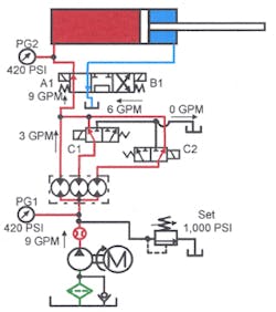
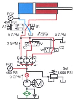
There are ways to use a fixed-volume pump and rotary flow dividers to change speeds with minimal heat generation. Figures 11-26 through 11-33 depict some of these. These circuits only give fixed preset speeds without changing hardware.
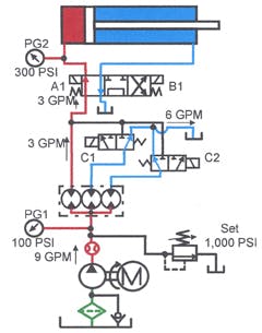
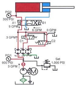
Figure 11-26 shows a 3-speed flow control circuit using a rotary flow divider. Here the cylinder is extending slow speed. With the circuit set up as shown, it defaults to slow speed. Notice there are no flow controls. To split pump flow evenly and reduce energy loss, use a rotary flow divider at its outlet. Each outlet of the flow divider will put out about 3 gpm.
In Figure 11-26 the cylinder is getting 3 gpm of oil and requires a pressure of 300 psi to move. Note that the pump pressure is only 100 psi. This happens because the flow divider is taking in 9 gpm and using 3 gpm to do work. The other two 3-gpm flows are going back to tank at 0 psi. While it appears these two 3-gpm flows waste energy, they are actually transferring their energy through the common to the left-hand motor. The left-hand motor becomes a pump with a 100-psi inlet and two motors driving it to 300 psi. As always in flow-divider circuits, the average of the sum of the outlets will be the inlet pressure. (300 psi + 0 psi + 0 psi = 300 psi; divide by 3 to get 100 psi.) With this system, cylinder speed slows, but the only energy loss is the inefficiency of the components used.
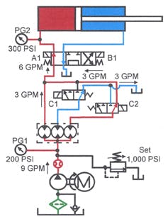
To get mid speed, the directional valves shift as indicated in Figure 11-27. By energizing solenoid C2 on the right-hand 3-way valve, an extra 3 gpm goes to the cylinder to give mid speed. Note that the pump pressure rises to 200 psi as the cylinder speed doubles. There still is only hardware inefficiency to waste energy, so the system runs cool.
To make the cylinder stroke at fast speed, shift the directional valves as shown in Figure 11-28. By energizing solenoids C1 and C2, both 3-way valves shift to send all pump flow to the cylinder. While the cylinder is in fast speed mode, pump and cylinder pressure are the same.
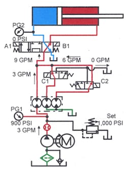
To retract the cylinder at fast speed, shift solenoid B1 along with C1 and C2, as shown in Figure 11-29. Energizing one or more solenoids in the retract mode gives different speeds that are nearly the same as when extending.
If the flow divider had more and/or unequal-size motors, selection of a combination of speeds by selecting different flow outputs is possible.
This circuit is tamper-proof. To change the preset speeds, the flow divider and/or pump must be changed.
Note: Any flow-divider circuit will intensify pressure. In Figure 11-26, if the cylinder stalled, the pressure would continue to rise. When the pump reached the relief valve setting, pressure at the cylinder would be 3000 psi. Use a second pressure-relief valve between the flow divider and the pump port of the cylinder directional valve to set a safe pressure in case of cylinder stall.
Speed control with rotary flow dividers
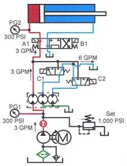
Figures 11-30 through 11-33 show a different type of rotary flow-divider circuit for variable speed. This circuit uses a smaller pump, electric motor, and tank to give the same speed but less high-speed force. Notice there is a 3-gpm pump supplying one section of the flow divider. As the fed section of the flow divider turns, the other two sections also turn and pump fluid directly from the tank. Thus, in Figure 11-30, the two right-hand sections of the flow divider are only circulating oil. All pump flow is going to the cylinder, which is operating in slow-speed mode. In this condition, the cylinder is capable of generating its highest tonnage. Notice that the cylinder requires 300 psi to move it and the pump is showing 300 psi.
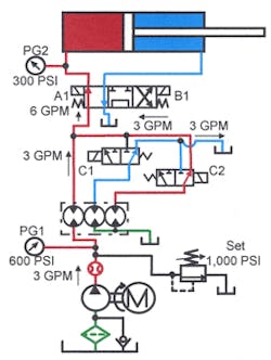
The cylinder speeds up when solenoid C2 on the left-hand 3-way valve is energized as in Figure 11-31. Now, one flow divider section sends its oil to the cylinder along with pump flow. The cylinder goes to mid-speed mode and pump pressure climbs to 600 psi.
To get full speed from the cylinder, solenoid C1 on the right-hand 3-way valve is energized as shown in Figure 11-32. Now all three sections of the flow divider feed the cylinder. The cylinder is at fast-speed mode and pump pressure climbs to 900 psi.
If the pressure required to move the cylinder to the work is relatively low, this circuit works well. There is enough flow to move rapidly at low pressure, and enough pressure at low flow to do the work.
Note: The gears in standard motor-type flow dividers are noisy. In the above two systems, the flow divider turns continuously. The noise level may be unacceptable in low-noise areas.
Rotary flow divider in full-time regeneration circuit
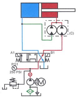
Figures 11-34 through 11-44 show a unique regeneration circuit using a rotary flow divider. Normally flow-divider circuits use the split flow to synchronize actuator movement. This circuit uses a flow divider to intensify flow for regeneration. This circuit works best on cylinders with small rods; and gives exactly twice speed on double-rod cylinders and hydraulic motors.
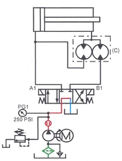
Figure 11-34 shows the circuit in the at-rest condition. Equal-outlet rotary flow divider C is piped between the cylinder rod-end port and the directional valve. The flow divider’s normal inlet port connects to the cylinder; one outlet connects to the directional valve; and the other outlet is teed into the cylinder cap-end line.
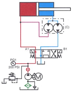
Figure 11-35 depicts solenoid A1 energized so that flow from the pump goes past the teed-in flow divider line to the cylinder cap end. As the cylinder extends, oil from the rod end enters the flow divider. The flow divider splits this oil. Half goes to tank at 0 pressure and half goes to the cylinder cap-end tee at pressure high enough to mix it with pump flow. As the cylinder starts to extend, speed quickly increases to almost twice the original speed. Maximum cylinder speed directly relates to the rod size: the larger the rod, the slower the speed. With a double rod-end cylinder, speed exactly doubles. As with any regeneration circuit, speed increases but force decreases.
Figure 11-36 shows the cylinder retracting. Energizing solenoid B1 of the 4-way directional valve sends pump flow to one outlet of the flow divider. Both of the motors in the flow divider turn at the rate of flow from the pump. During this part of the cycle, the motor that has its inlet teed into the cap-end line becomes a pump. Pump flow plus the same flow from the second motor makes the cylinder retract twice as fast as a conventional circuit. (However, cylinder thrust is only half that of a conventional circuit.) This flow-divider regeneration circuit doubles the cylinder speed without making the pump work harder. Size the pump, valve, tank, and piping up to the regeneration circuit according to pump flow. The only high flows are at or very near the cylinder.
Using a motor with a higher displacement on the left-hand side of the flow divider increases speed even more. The limit is reached when pressure to run the cylinder at the faster rate exceeds the relief valve setting. When using unmatched motors, make sure the line from the cylinder cap-end to the motor will handle the higher suction flow.
Rotary flow-divider regeneration circuit – pressure-activated to full thrust
When it is necessary to get out of regeneration and into full thrust, add other valves to the rotary flow-divider regeneration circuit.
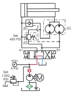
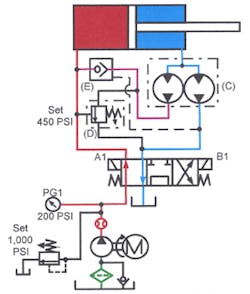
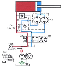
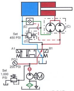
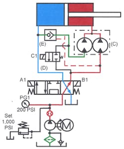
The regeneration circuit shown at rest in Figure 11-37 can be pressure activated to produce full thrust. Equal flow divider C is piped between the 4-way directional valve and the cylinder. The normal inlet port connects to the cylinder; one outlet connects to the directional valve; and the other outlet passes flow freely through pilot-operated check valve E to a tee in the cylinder cap-end line. Pilot-operated check valve E gets its pilot signal from the cylinder rod-end line before the flow divider port. Teed into the line between the flow divider and check E is the inlet to sequence valve D. Sequence valve D’s outlet tees into the cylinder rod-end line. Sequence valve D is internally drained and gets its external pilot signal from the cylinder cap-end line.
In Figure 11-38, solenoid A1 is energized so flow from the pump goes past the tee in the flow divider line to the cylinder cap-end. As the cylinder extends, oil from the rod end enters the flow divider. This oil splits; half goes to tank at no pressure, and half free-flows through pilot-operated check valve E to the cylinder cap-end tee at a pressure high enough to mix with pump flow. When the cylinder starts to extend, its speed quickly increases to almost twice speed. Maximum cylinder speed directly relates to the rod size. The larger the rod, the slower the speed. For a double rod-end cylinder, speed exactly doubles. As with any regeneration circuit, speed increases but force decreases.
When the cylinder meets resistance, pressure increases. When the cylinder butts against the work, as in Figure 11-39, pressure build up in the cap-end line pilots sequence valve D open. When sequence valve D opens, oil from both sides of the flow divider returns to tank at no pressure. At the same time, pilot-operated check valve E closes to keep the pump from relieving to tank. With the rod end of the cylinder hooked to tank and the pump feeding the cap end, the cylinder produces full thrust.
In Figure 11-40, the cylinder is retracting. By energizing solenoid B1, the 4-way directional valve sends pump flow to one outlet of the flow divider. Both of the motors in the flow divider turn at the rate of flow from the pump. During this part of the cycle, the motor — with its inlet teed into the cap-end line — acts as a pump. Pilot pressure from the cylinder rod-end port opens pilot-operated check valve E to allow this flow. Pump flow, plus the same flow from the second motor, makes the cylinder retract twice as fast as a conventional circuit. Again, however, cylinder thrust is only half that of a conventional circuit.
Rotary flow divider regeneration circuit — solenoid-activated to full thrust
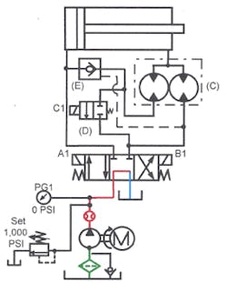
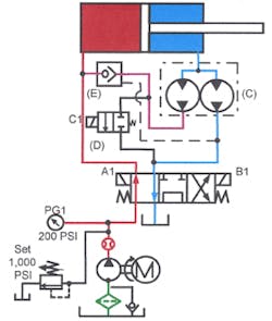
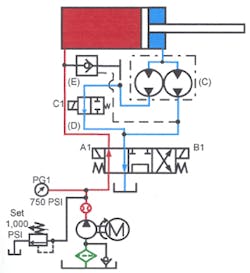
Other valves added to the rotary flow-divider regeneration circuit produces an arrangement that can be switched to full thrust by activating a solenoid. Shown with the circuit at rest in Figure 11-41, equal-output flow divider C is piped between the 4-way directional valve and the cylinder. The flow divider’s normal inlet port connects to the cylinder; one outlet connects to the directional valve; and the other outlet passes flow freely through pilot-operated check valve E to a tee in the cylinder cap-end line. Check valve E receives its pilot signal from the cylinder rod-end line before the flow divider port. Teed into the line between the flow divider and the check valve is the inlet to normally closed directional-control valve D. Valve D’s outlet tees into the cylinder rod-end line. Valve D is direct solenoid operated and thus does not need a pilot supply.
When solenoid A1 of the main directional valve is energized — as in Figure 11-42 — flow from the pump goes past the flow divider line to the cylinder. As the cylinder extends, oil from its rod end enters the flow divider. The flow divider splits this oil; half of it goes to tank at no pressure, and the other half of it passes freely through pilot-operated check valve E to the cylinder cap end at a pressure high enough to mix it with pump flow. As the cylinder moves, its speed almost doubles. The amount of speed increase is directly related to the size of the piston rod. The larger the rod, the slower the speed. A double rod-end cylinder would go exactly twice as fast. As with any regeneration circuit, the speed increases but force decreases.
When the cylinder rod trips a limit switch, as in Figure 11-43, the switch sends an electrical signal to solenoid-operated 2-way directional valve D, causing it to open. When valve D opens, oil from both sides of the flow divider returns to tank at no pressure. The cylinder slows before it contacts the work with this arrangement. At the same time, pilot-operated check valve E closes to prevent pump flow from bypassing to tank also. With the rod end of the cylinder connected to tank and the pump feeding the cap end, the cylinder generates full thrust.
In Figure 11-44, the cylinder is retracting. Energized solenoid B1 shifts the 4-way directional valve to send pump flow to one outlet of the flow divider. Both of the motors in the flow divider turn at the rate of flow from the pump. During this part of the cycle, the motor — with its inlet teed into the cap-end line — acts as a pump. Pilot pressure from the cylinder rod-end port opens check valve E to pass this flow. Pump flow, plus the same flow from the second motor, makes the cylinder retract twice as fast as a conventional circuit. However, cylinder thrust is only half that of a conventional circuit.
Rotary flow divider as an intensifier
As noted earlier, a rotary flow divider intensifies pressure at one outlet when the other outlet is at a lower or 0 pressure. In the case of a 2-outlet motor-type flow divider with equal displacements, if the inlet pressure is 1000 psi, one outlet can be at 2000 psi while the other outlet is at 0 psi. While pressure doubles, flow from the intensified outlet is one half that at the inlet. The energy from the outlet motor with 0 pressure transfers to the other motor via the common shaft, thus intensifying the pressure.
With more than one section going to tank — say a 4-outlet divider with three outlets to tank — intensification would quadruple the pressure. While the intensified fluid reaches that pressure, volume is only one-fourth of inlet flow.
Using rotary flow dividers with unequal sections is another way to get high intensification. If the motor in one section discharges 3 gpm to tank and the other section discharges 1 gpm. Intensification is still 4:1.
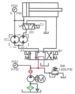
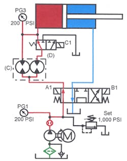
Figures 11-45 through 11-48 depict how to use this feature of motor-type flow dividers in a circuit. This circuit has equal-outlet flow divider C and 3-way directional valve D in the cylinder cap-end line. In the at-rest condition, shown in Figure 11-45, both outlets of the flow divider connect to the cap-end port.
In Figure 11-46, the cylinder is extending at full speed and low thrust. Energizing solenoid A1 shifts the directional valve to pass oil through one side of the flow divider and the 3-way valve to the rod-end port. Fluid from the other side of the flow divider goes directly to the cylinder rod-end port. The pump and valves must be sized to handle enough flow for the speed required during the fast-forward portion of the cycle. (Normally, motor horsepower is low for a cylinder moving a light load.)
When the cylinder contacts the limit switch, as in Figure 11-47, the switch energizes solenoid C1 on the 3-way valve. The valve shifts and oil from one section of the rotary flow divider then goes to tank. Pressure doubles while cylinder speed drops to half what it was before solenoid C1 was energized.
This circuit works best on actuators that are not required to stall. Using this setup for a fast advance followed by a clamping operation might result in excess heat because internal leakage in the flow divider while the cylinder is holding.
Energizing solenoid B1, as in Figure 11-48, makes the cylinder retract. Oil from the cap-end port goes through both sections of the flow divider and back to tank through the directional valve.
When using a motor-type flow divider as an intensifier, make sure it is capable of operating at the elevated pressure. The pressure rating of an inexpensive gear-motor-type flow divider may be only 2000-psi intermittent and 1500-psi continuous. On the other hand, some gerotor-type flow dividers handle as much as 4500-psi intermittent and 3000-psi continuous — at a higher price.
