Regeneration Circuits
A regeneration circuit can double the extension speed of a single-rod cylinder without using a larger pump. This means that regeneration circuits save money because a smaller pump, motor, and tank can produce the desired cycle time. It also means that the circuit costs less to operate over the life of the machine.
A regeneration circuit can also replace a double rod-end cylinder in some circuits. With equal rod diameters, a double-rod cylinder’s area is the same on both ends. Equal areas mean identical force and speed both ways at a given pressure and flow. Reciprocating tables often use double rod-end cylinders for this reason. When the main function of a double rod-end cylinder is equal speed and power in both directions of travel, replace it with a regeneration circuit.
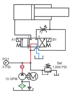
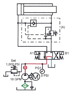
A double rod-end cylinder costs more than a cylinder with a single oversize rod; the extra rod needs space in which to move; and the second rod seal is another potential leakage source. To eliminate these objections, use the full-time regeneration circuit shown in Figures 17-6 and 17-8. Extension and retraction speed (as well as thrust) is the same, without the extra rod and its problems.
One disadvantage to using cylinders with a single oversize rod is that speed and thrust are not identical if the rod diameter ratio is not exactly 2:1. Most cataloged 2:1 rod diameters are only close to that ratio. A standard NFPA 3.25-in. bore cylinder comes with a 2.00-in. diameter rod as a 2:1 differential. If using this cylinder in a full-time regeneration circuit, speed is about 21% faster on the extension stroke, with about 21% less force than the retraction stroke.
This chapter explains regeneration principles and shows several common circuit designs, as well as some uncommon and unique circuits.
Regeneration principles
Applying fluid flow to both ports of a single-rod cylinder makes it extend -- or at least try to extend. Because areas on opposite sides of the piston are unequal, the cap end of the cylinder always has more force than the rod side.
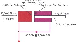
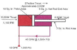
Figure 17-1 shows forces and speeds that result when using a cylinder with a 10-in.2 piston area and a 2-in.2 rod area. This cylinder has a rod differential of approximately 1.25:1.
Applying 10-gpm flow to both ports of the cylinder makes it extend at a rate of 1155 ipm. The effective cylinder thrust as it moves forward at 1000 psi is 2000 lb. The same cylinder, with 10 gpm flowing into the cap end while the rod end is connected to tank, would extend at 231 ipm or 1/5 the speed of the regeneration circuit.
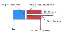
Figure 17-2 shows the forces and speeds of this same cylinder as it retracts. Thrust is 8000 lb, but speed is only 288 ipm.
Often when a cylinder with a small rod is piped for regeneration, it will not even try to extend at a reasonable working pressure. This is because the extension force is too low to overcome cylinder friction, machine force requirements, and pressure drop due to high flow from rod end to cap end. Even if the cylinder does extend, low force may make it useless. Notice also that extension speed is very fast and retraction speed is very slow.
Most regeneration circuits use cylinders with a 2:1 rod ratio. A 2:1 rod cylinder has a rod area equal to half the piston area. In actual use, extend and retract speed and power is identical with an area differential of exactly 2:1. All of the cylinders in the following examples have 2:1 ratios.
Regeneration with a 2:1 rod
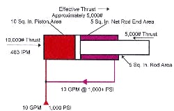
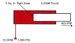
Figure 17-3 shows a 2:1 rod cylinder in regeneration. Notice the difference in force and speed using the same flow and pressure as Figure 17-1. These figures assume an exact 2:1 rod. In actual practice only specially made cylinders have an exactly 2:1 area ratio.
With a 2:1 rod, force and speed on the extension and retraction stroke is identical. As Figure 17-4 shows, a regenerating cylinder acts like a ram-type cylinder. In effect, a cylinder in regeneration does not need a piston. Because both ports connect to the same power source, the effect of the piston area outside the rod diameter is cancelled. Pressure on both sides of the annulus area around the rod makes the piston area here useless. As the cylinder extends in regeneration, force is half while speed doubles.
During regeneration there is no flow to tank. All oil from the pump goes to the cylinder. All fluid from the rod end of the cylinder mixes with pump flow and goes to the cap end. The exchange of rod end fluid, added to pump oil going to the cap end, doubles the cylinder’s speed.
Figure 17-5 shows force and speed when a 2:1 oversize rod cylinder retracts. Pump flow of 10 gpm enters the rod port and the cylinder retracts using the 5-in.2 annulus area. Speed during retraction is the same as when the cylinder regenerates forward. Flow from the cylinder cap end port is twice pump flow as it retracts because cap end area is twice rod end area. A conventional regeneration circuit has double flow through the valving while the cylinder extends and retracts.
The rest of this section shows many regeneration circuits with explanations of how they work. Different circuits have various features that make them better for certain applications. Some circuits are just a different way of connecting the same parts.
Full-time regeneration
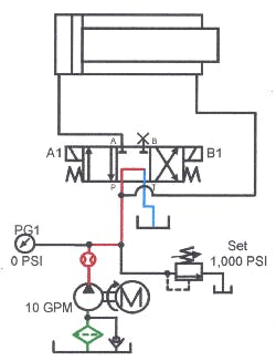
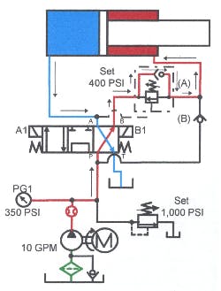
The regeneration circuit in Figures 17-6 through 17-8 replaces a double-rod-end cylinder circuit used to produce equal speed and power in both directions of travel. The schematic diagram shows a tandem-center, 3-position, 4-way directional valve, connected to a 2:1 rod cylinder. Port A of the directional valve connects to the cap-end port of the cylinder. The rod-end port of the cylinder tees into port P of the directional valve. In the at-rest condition shown in Figure 17-6, the pump unloads to tank while the cylinder sits still.
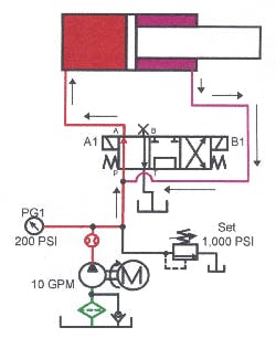
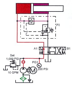
To extend the cylinder, energize solenoid A1 as in Figure 17-7. Energizing solenoid A1 connects the pump to the cap end of the cylinder to make it extend. Oil leaving the rod end of the cylinder mixes with pump flow and regenerates to the cap end of the cylinder through the directional valve. Supplementing pump flow with rod flow makes the cylinder extend twice as fast as a conventionally piped circuit.
At first it appears that the cylinder only goes 50% faster. If 10 gpm goes in the cap end of a 2:1 rod cylinder, only 5 gpm comes out of the rod end. This puts 15 gpm into the cap end for a 50% increase in speed. However, once 15 gpm goes into the cap end, 7.5 gpm comes out of the rod end. Now there is 17.5 gpm going into the cap end. Continuing this scenario shows that flow from the cylinder’s rod end -- as it extends in regeneration -- almost immediately reaches 10 gpm to produce double cylinder speed.
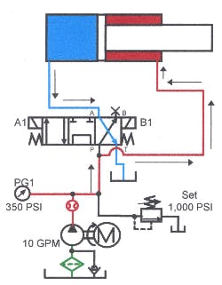
Figure 17-8 shows the cylinder retracting. Pump flow goes directly to the rod-end port and the cylinder retracts. Oil from the cap-end port returns to tank through the directional valve. Note that in a full-time regeneration circuit, the directional valve handles twice pump flow in both directions of travel. If the valve were sized for just pump flow, excess pressure drop would slow cylinder speed and add to system heating.
In Figure 17-9, a needle valve has been teed into the rod-end line and connected to port B. Use this needle valve to adjust maximum speed when the cylinder extends. This circuit is useful when standard speed is too slow but double speed is too fast. It is a bleed-off flow-control circuit, which means opening the valve reduces speed. Also, for accurate speed control, use a pressure-compensated flow-control valve in this circuit.
Regeneration circuit – pressure-actuated to full thrust
Regeneration circuits move a cylinder rapidly to the work, but only have half power at work contact. For machines that need full cylinder force to do their jobs, divert regeneration flow to tank after work contact. The full force portion of the stroke is only half as fast as approach speed. The half-speed work stroke poses little problem because it usually is a small portion of the cycle.
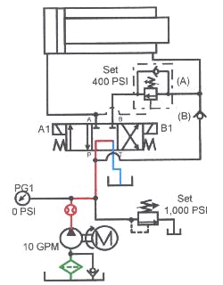
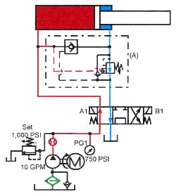
Figures 17-10 through 17-13 show a regeneration circuit that changes to full thrust when pressure reaches a predetermined setting. The addition of externally piloted sequence valve A and check valve B to the circuit makes this possible. When pressure rises, sequence valve A shifts to connect the rod end of the cylinder to tank, eliminating backpressure. Because sequence valve A has an external pilot, it opens fully as pressure builds in the cylinder’s cap end.
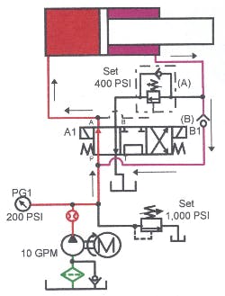
Figure 17-11 shows the cylinder regenerating forward. During this part of the cycle pump oil goes to the cap end of the cylinder through the directional valve. Oil from the rod end free flows through check valve B to mix with pump flow -- passing through the directional valve to the cylinder’s cap end also. Sequence valve A stays closed because its pressure setting is higher than the pressure it takes to move the regenerating cylinder. The setting of sequence valve A is easy to establish while the circuit runs. Start with a high-pressure setting and slowly lower it as the cylinder extends until speed starts to slow. When speed slows, raise the setting until speed is maximum, then go another half turn higher. The cylinder continues to extend at twice speed and half power until it meets added resistance.
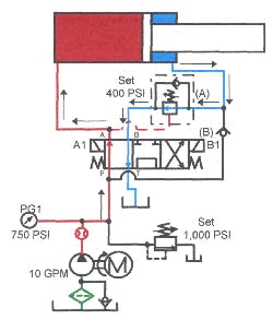
When extra resistance raises cylinder cap-end pressure high enough to pilot sequence valve A open, as in Figure 17-12, oil from the cylinder’s rod end goes directly to tank. With this flow going to tank, forward speed decreases as rod-end pressure drops. No backpressure means the cylinder is capable of full tonnage but only moves half as fast. During this part of the cycle, check valve B blocks pump flow from going to tank through sequence valve A.
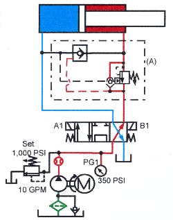
To retract the cylinder, energize solenoid B1 of the directional valve as in Figure 17-12. Pump flow now goes through the directional valve, around the free-flow check valve in sequence valve A, and into the rod end of the cylinder. As the cylinder retracts, oil from the cap end goes to tank through the directional valve.
This sequence circuit provides rapid advance speed, followed by full force to clamp, punch, or operate with different size parts. The cylinder moves rapidly until it contacts a part, then changes to full force. As with any sequence circuit there is no guarantee pressure build-up came from work contact. Anytime pressure increases enough, the circuit automatically shifts out of regeneration into full force. Another down side of this circuit is that the cylinder hits the part at full speed. This impact might cause damage to the machine, tooling, or parts. To avoid these problems, consider a circuit that drops out of regeneration electrically.
Regeneration Circuit
Regeneration circuit – solenoid-actuated to full thrust
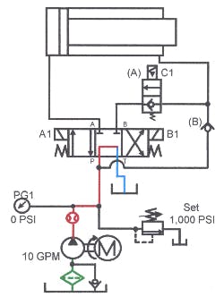
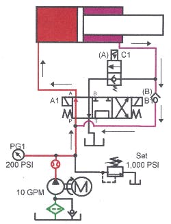
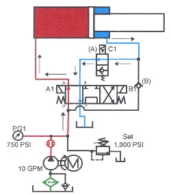
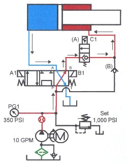
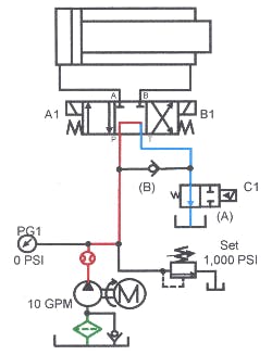
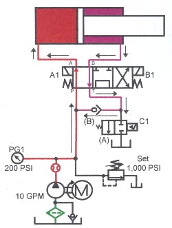
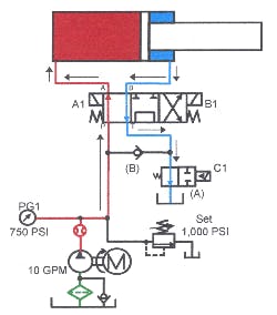
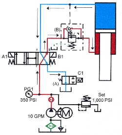
Figures 17-14 through 17-17 show a standard regeneration circuit that changes to full thrust and half speed on demand. Shifting a solenoid-operated valve any place in the stroke slows the cylinder’s advance and sets up the circuit for full tonnage. Addition of solenoid pilot-operated 2-way valve A and check valve B to the circuit makes this possible. When the cylinder reaches a limit switch, 2-way valve A shifts to connect the rod end of the cylinder to tank, eliminating backpressure.
In Figure 17-15, cylinder is depicted extending in regeneration. During this part of the cycle, oil from the pump goes to the cap end of the cylinder. Oil from the rod end flows freely through check valve B to mix with pump flow and go back into the cylinder. Two-way directional valve A remains closed. The cylinder advances at double speed and half power.
When the moving cylinder makes the limit switch, an electrical signal energizes the solenoid on valve A as in Figure 17-16. Valve A opens and oil from the cylinder’s rod end flows directly to tank. With the cylinder’s rod-end flow going to tank, pressure drop there allows the cylinder to produce full force while stroking at half speed. During this part of the cycle, check valve B blocks pump flow from going to tank through 2-way valve A. With this arrangement, cylinder speed is slowed before contacting the part because the limit switch drops it out of regeneration. The result: less shock to the system and damage to the machine, tooling, or parts.
To retract the cylinder, energize solenoid B1 of the directional valve as in Figure 17-17. Pump flow goes through the 4-way directional valve and flows freely through the check valve in 2-way valve A, then into the rod end of the cylinder. As the cylinder retracts, oil from the cap end flows to tank through the 4-way directional valve. (Note: when using a 2-way valve without reverse free-flow capability, either leave the solenoid on the 2-way valve energized, or install a bypass check around it.)
Other regeneration circuits
Some of the following circuits use a solenoid or a pressure-control valve to disable regeneration but the placement of the valves is different. Some of these circuits have specific advantages; some are just another way of doing the same thing.
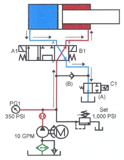
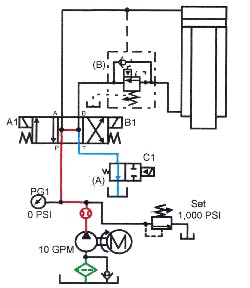
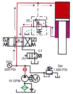
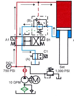
Figures 17-18 through 17-21 show a different way to pipe a solenoid-actuated regeneration circuit. (The results are the same as the previous circuit. There is no particular advantage to this configuration.) Figure 17-18 depicts a standard valve and cylinder circuit with the addition of 2-way normally open directional valve A and check valve B. At rest, the pump unloads through the tandem-center directional valve and 2-way valve A.
In Figure 17-19, both solenoid A1 on the 4-way valve and solenoid C1 on the 2-way valve are energized. Pump flow goes through the 4-way valve to the cylinder’s cap-end port. Oil returning from the cylinder goes through check valve B to mix with pump flow and regenerates to the cylinder’s cap end. Cylinder speed is twice that of a conventional circuit, but force is one half.
When the cylinder makes the limit switch, valve A shifts, Figure 17-20, opening a free path for oil from the rod end to flow to tank. During this part of the cycle, check valve B closes to prevent pump flow from going to tank also. Now the cylinder is capable of full thrust at half speed.
In Figure 17-21, solenoid B1 on the 4-way valve is energized to retract the cylinder. Pump oil goes to the rod end of the cylinder while oil from the cap end returns to tank through the 4-way and the 2-way valves.
Caution: make sure the tank line of the 4-way directional valve used in this circuit is capable of operating with the amount of backpressure generated.
Circuit Solenoid Actuated to Full Thrust
Regeneration circuit – solenoid-actuated to full thrust
Figure 17-22 shows another way to alter and operate the previous solenoid-actuated regeneration circuit. Add 2-way normally open directional valve A to the standard valve and cylinder circuit. At rest, the pump unloads through the open-center directional valve and valve A. This circuit also has counterbalance valve B to resist a running away load situation. Note that counterbalance valve B has an external drain port. The external drain is necessary on this circuit because outlet flow from the counterbalance valve sees pressure while oil regenerates. Backpressure from regeneration would prevent an internally drained counterbalance valve in this circuit from opening. The cylinder would not extend with the counterbalance valve closed.
In Figure 17-23, solenoid C1 on directional valve A is energized to start the cylinder forward. Pump flow goes through the 4-way directional valve to the cylinder. Oil returning from the cylinder’s rod end flows through the open-center 4-way directional valve, mixes with pump flow, and enters the cylinder’s cap end. Cylinder speed is twice as fast as a conventional circuit while force is only half. When the cylinder contacts the limit switch, it deenergizes solenoid C1 and energizes solenoid A1 on the 4-way directional valve, as in Figure 17-24. Pump oil still flows to the cylinder’s cap end, but flow from the rod end now passes freely to tank. The cylinder is now capable of full thrust at half speed.
In Figure 17-25, solenoid B1 on the 4-way directional valve is energized. Pump oil now goes to the rod end of the cylinder while oil from the cap end returns to tank through the 4-way and the 2-way directional valves. Note: while this hook-up eliminates the check valve, it complicates the electrical circuit slightly.
CAUTION: Make sure the tank line of the 4-way directional valve used in this circuit is capable of operating with the amount of backpressure generated.
Regeneration circuit – solenoid-actuated to full thrust
Figures 17-26 through 17-29 show another way to pipe a solenoid-actuated regeneration circuit. The results are the same as the previous circuit, but the components it uses eliminate most of the piping and potential leaks.
Figure 17-26 indicates a series bar manifold with two open-center directional valves: a double-solenoid 4-way and a single-solenoid 3-position valve. At rest, the pump unloads through the open centers on the directional valves. The single-solenoid valve takes the place of the 2-way valve in the previous circuit.
Energizing solenoid A2 on the single-solenoid directional valve, as in Figure 17-27, sends pump flow through the open center of the 4-way valve to the cylinder’s cap end. Oil returning from the cylinder’s rod end mixes with pump flow through the open center of the double-solenoid 4-way and goes into the cylinder’s cap end. Speed is twice that of a conventionally piped circuit while the force is only half.
When the cylinder makes the limit switch, Figure 17-28, it deenergizes solenoid A2 on the single-solenoid valve and energizes solenoid A1 on the 4-way directional valve. Pump oil still goes to the cylinder’s cap end but flow from the rod end passes freely to tank. Cylinder speed is half of that of regeneration, but now full cylinder force is available.
Figure 17-29 shows solenoid B1 on the 4-way directional valve energized for retraction. Pump oil goes to the rod end of the cylinder and oil from the cap end returns to tank through the 4-way and the open center of the single-solenoid directional valve.
The advantages of this circuit are ready availability of the valves, shorter installation time, and fewer potential leaks.
CAUTION: again make sure the tank line of the 4-way directional valve used in this circuit is capable of operating with the amount of backpressure generated.
Pressure actuated to full thrust
Regeneration circuit – pressure actuated to full thrust
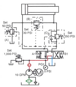
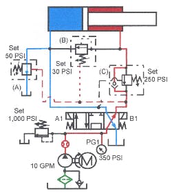
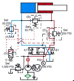
Large cylinders at high flows need large, expensive directional valves to handle the double flow of a regeneration circuit. Also, when cylinders with regeneration circuits are located at some distance from the directional valve, pressure drop at high regeneration flows might be a problem. The circuit in Figure 17-30 uses pressure-control valves near the cylinder to handle regeneration flows, so that the directional valve only sees pump flow. This circuit drops out of regeneration after pressure increases at load contact. Valve B opens under low pressure to route rod-end oil to the cap end. Its operation is like a sequence valve so it uses an external drain. In this circuit the external drain goes to tank through the rod-end port. Porting the drain here keeps the sequence valve from opening when the cylinder retracts. Valve C direct oil from the rod end to the cap end until load pressure builds. This valve is similar to a counterbalance valve. (Set pressure on valve C high enough to make sure the cylinder regenerates.) Pressure valve A dumps part of cap-end flow to tank when the cylinder retracts. This keeps part of the high return flow away from the 4-way valve to reduce backpressure during cylinder return.
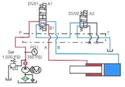
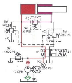
Figure 17-31 shows the cylinder extending in regeneration. Energizing solenoid A1 shifts the 4-way directional valve to send oil to the cylinder’s cap end. Oil from the cylinder’s rod end opens low-pressure sequence valve B and regenerates to the cap end. Counterbalance valve C stays closed because its pressure setting is higher than regeneration pressure. Set sequence valve B as low as possible to minimize backpressure. Set counterbalance valve C high enough to make sure the cylinder regenerates -- and low enough to open easily when the cylinder meets resistance. Valve A stays closed when the cylinder extends because its pilot supply comes from the rod port after counterbalance valve C.
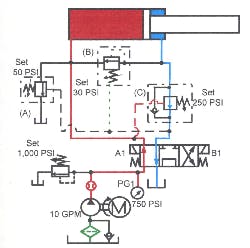
When the cylinder meets resistance, Figure 17-33, pressure builds up in the cap-end port and opens externally piloted counterbalance valve C. When counterbalance valve C opens, it lets rod-end flow go directly to tank. Pressure drop at sequence valve B lets it close to stop regeneration. This drops all backpressure at the cylinder’s rod end so it is capable of full thrust.
To retract the cylinder, energize solenoid B1 of the 4-way directional valve, as in Figure 17-33. Oil flows through the bypass check of counterbalance C to the cylinder’s rod end. Rod-end pressure at the external drain line of sequence valve B holds it closed so fluid cannot bypass to tank. The cylinder retracts with part of the cap-end oil going through the directional valve and excess flow through valve A directly to tank. Pressure-control valve A gets an external pilot signal from the cylinder’s rod end line to open it for retraction.
In the at rest condition the cylinder could extend due to external forces because fluid can pass through sequence valve B from rod to cap at any pressure above 30 psi. If this happens, add a pilot-operated check valve in the line between sequence valve B and the rod port.
Regeneration circuit – solenoid-actuated to full thrust
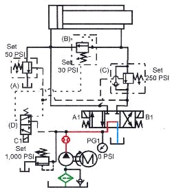
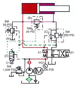
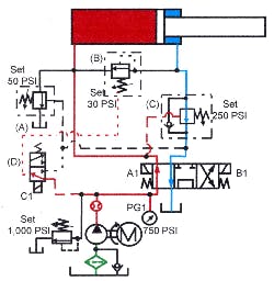
The circuit in Figures 17-34 through 17--37 is the same as in Figures 17-30 through 17-33 except that the change from regeneration to full thrust is solenoid controlled. The circuit in Figure 17-34 uses pressure-control valves near the cylinder to handle the high regeneration flows, so the directional valve only sees pump flow. This circuit drops out of regeneration after making the limit switch.
Pressure valve B opens under low pressure to route oil from the rod end to the cap end. The valve’s operation is like a sequence valve, so use an external drain. In this circuit, the external drain goes through 3-way directional valve D to the rod-end port, then to tank. With the drain here, sequence valve B will not open when the cylinder retracts. Directional valve D closes sequence valve B from an electrical command to stop regeneration.
Valve C directs oil from the rod end to the cap end until pressure rises enough to pilot it open. This valve acts as a counterbalance, so set it high enough to make sure the cylinder regenerates, but low enough to minimize energy loss.
Pressure valve A dumps part of the cap end flow to tank while the cylinder retracts. This keeps high flow away from the 4-way valve to reduce backpressure during the return stroke.
Figure 17-35 shows the cylinder extending in regeneration. Solenoid A1 of the 4-way directional valve shifts it, porting oil to the cylinder’s cap end. Oil from the rod end passes through sequence valve B to the cap end. Valve C stays closed because pressure during regeneration is not enough to pilot it open. (Set valve C high enough to make sure the cylinder regenerates, but low enough to operate easily after energizing 3-way valve D. Valve A stays closed while the cylinder extends because its pilot oil comes from the rod port after counterbalance valve C.
When the cylinder contacts the limit switch in Figure 17-36, 3-way directional valve D shifts and sends pump pressure to the drain port of sequence valve B. Pressure in the drain port of sequence valve B closes it to block flow from the rod end to the cap end. Pressure rise in the cap port opens externally piloted counterbalance valve C to give rod-end oil a path to tank. Because oil from the rod end has a free path to tank, the cylinder now is capable of full thrust.
To retract the cylinder, energize solenoid B1 of the 4-way directional, as in Figure 17-37. Oil goes through the bypass check of counterbalance C to the cylinder’s rod-end port. The cylinder now retracts, with part of the oil from the cap end going to tank through the directional valve and part through dump valve A. Pilot pressure from the cylinder’s rod-end line opens pressure valve A to dump excess fluid.
Regeneration circuit with poppet-type cartridge valves
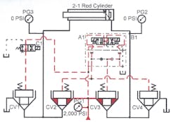
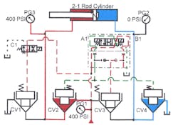
For circuits with flows above 60 to 100 gpm, poppet-type cartridge valves are an option. This type of valve, sometime called a logic valve is a simple pilot-to-close check valve. Because check valves are 2-way valves, four of them are needed to operate a double-acting cylinder. The main advantage of using logic valves in a regeneration circuit is the way they handle high flows. Another reason is, larger cartridges handle double flow during regeneration and cylinder retract in these flow paths only.
With a 150-gpm pump cycling a 2:1 rod cylinder, flow to the cylinder is 150 gpm. Flow from the rod end of the cylinder extending is, 75 gpm, and 300 gpm from the cap end when retracting. With a conventional 4-way valve this 150-gpm-pump circuit requires a 300-gpm valve. A valve this size is expensive, big, and overkill for all but the regeneration and retract part of the cycle.
In the circuit covered by Figures 17-38 through 17--41, size logic valve CV1 to handle 75 gpm, logic valve CV2 for 150 gpm, and logic valves CV3 and CV4 for 300 gpm. Smaller cartridges are less expensive and take less space, while larger cartridges give high flow at low pressure drop.
Figure 17-38 shows the circuit at rest with the pump running. Pilot pressure through two directional valves holds all logic valves closed. A regeneration circuit requires two pilot valves for limit switch changing from regeneration to full force. Use a pressure-control valve in place of the single-solenoid pilot valve when transition from regeneration to full force is due to pressure build up at work contact.
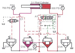
To extend the cylinder in regeneration, energize solenoid A1 of the 4-way double-solenoid directional valve, as in Figure 17-39. This drops pilot pressure on logic valve CV3, allowing pump flow to go to the cylinder's cap end. Oil from the cylinder’s rod end cannot get out of logic valve CV1 so pressure increases there until it forces logic valve CV2 to open. Then oil flows through logic valve CV2, mixes with pump flow, and both pass through logic valve CV3 to the cylinder. The cylinder extends at twice speed and half force till it contacts a limit switch.
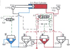
When the cylinder rod contacts the limit switch, it energizes solenoid C1 of the single-solenoid directional valve to let logic valve CV1 open, as in Figure 17-40. When logic valve CV1 opens, logic valve CV2 closes because regeneration pressure drops. With oil free flowing to tank through logic valve CV1, the cylinder is capable of full thrust at half speed.
Figure 17-41 shows solenoid B1 of the double-solenoid directional valve energized and the logic valve positioned to retract the cylinder. With solenoid B1 energized, pilot pressure drops on logic valve CV2 and CV4. Logic valves CV2 and CV4 open to pass pump flow to the cylinder’s rod end while cap end oil goes to tank.
A high-flow circuit normally costs less, and has lower pressure drop when using cartridge valves.
Motor-type flow divider in full-time regeneration circuit
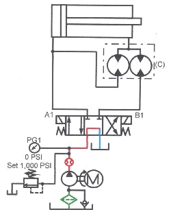
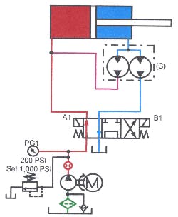
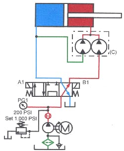
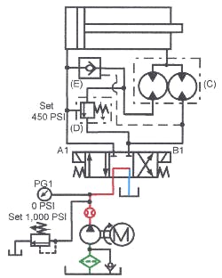
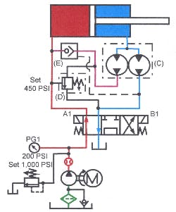
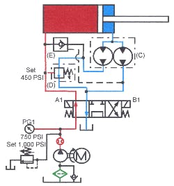
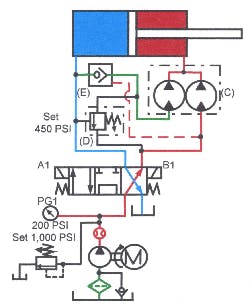
Figures 17-42 through 17-44 show a unique regeneration circuit using a motor-type flow divider. This regeneration circuit works best on small-rod cylinders and produces exactly twice the speed on double-rod cylinders and hydraulic motors.
A motor- type flow divider consists of two or more hydraulic motors in the same housing mounted on a common shaft so they all rotate at the same speed. The motors have a common inlet but separate outlets. If the motors are the same size, any fluid to the inlet divides equally at the outlets. Motors with different cir provides proportionally different outlet flows.
Normally, flow-divider circuits split the inlet flow to synchronize actuator movements, but they also can be used to increase flow for a regeneration circuit.
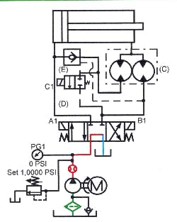
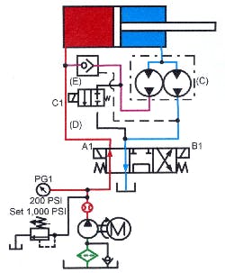
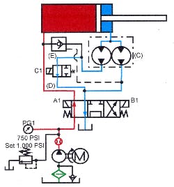
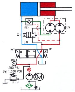
Figure 17-42 shows a regeneration circuit with a full-time motor-type flow divider in the at-rest condition. Piped between the cylinder’s rod end-port and the directional valve is equal-motor flow divider C. Its normal inlet port connects to the cylinder, one outlet connects to the directional valve, and the other outlet is teed into the cylinder’s cap-end line.
Figure 17-43 shows solenoid A1 energized so flow from the pump goes past the teed-in flow-divider line to the cylinder’s cap end. As the cylinder extends, oil from the rod end enters the flow divider. The flow divider splits that oil. Half flows to tank at no pressure, and the other half flows to the cylinder’s cap-end tee at pressure high enough to mix it with pump flow. As the cylinder starts forward, speed quickly increases to almost double. Maximum cylinder speed directly relates to the rod size. The larger the rod, the slower the speed. With a double-rod end cylinder, speed exactly doubles. As with any regeneration circuit, speed increases but force decreases.
Figure 17-44 shows the cylinder retracting. Energizing solenoid B1 shifts the 4-way directional valve to send pump flow to one outlet of the flow divider. Both of the motors in the flow divider turn at the rate of flow from the pump. During this part of the cycle, the motor with its inlet teed into the cap-end line acts as a pump. Pump flow, plus the same flow from the second motor, makes the cylinder retract twice as fast as a conventional circuit. Again, cylinder thrust is only half that of a conventional circuit.
This flow-divider regeneration circuit doubles the speed without making the pump work harder. Size the pump, valve, tank, and piping up to the regeneration circuit according to pump flow. The only high flows are at or very near the cylinder.
Using a motor with a higher cir on the left side of the flow divider increases speed even more. The limit is when pressure to run the cylinder at the faster rate, exceeds the relief valve setting. When using unmatched motors, make sure the line from the cylinder cap end to the motor will handle the higher suction flow.
Divider regneration circuit
Motor-type flow-divider regeneration circuit – pressure actuated to full thrust
When it is necessary to get out of regeneration and into full thrust, add other valving to the motor-type flow-divider regeneration circuit. Figure 17-45 shows such a regeneration circuit at rest. Piped between the 4-way directional valve and the cylinder is equal flow divider C. Its normal inlet port connects to the cylinder; one outlet connects to the directional valve; the other outlet passes flow through pilot-operated check valve E to a tee in the cylinder’s cap-end line. Check valve E gets its pilot signal from the cylinder’s rod-end line before the flow-divider port. Teed into the line between the flow divider and check valve E is the inlet to sequence valve D. The outlet of sequence valve D tees into the cylinder’s rod-end line. Sequence valve D is internally drained and gets its external pilot signal from the cylinder’s cap-end line.
Figure 17-46 shows solenoid A1 energized, with flow from the pump going past the teed in the flow-divider line to the cylinder’s cap end. As the cylinder extends, oil from the rod end enters the flow divider. The flow divider splits that oil. Half goes to tank at no pressure and half flow freely through pilot-operated check E, then goes to the cylinder’s cap-end tee at a pressure high enough to mix with pump flow. As the cylinder starts forward, speed quickly increases to almost double. Maximum cylinder speed directly relates to the rod size. The larger the rod, the slower the speed. With a double-rod end cylinder, speed exactly doubles. As with any regeneration circuit, speed increases but force decreases.
When the cylinder meets resistance, pressure builds. Figure 17-47 shows the cylinder against the work. Pressure build-up in the cap-end line pilots sequence valve D open. When sequence valve D opens, oil from both sides of the flow divider returns to tank at no pressure. At the same time, pilot-operated check E closes to keep the pump from relieving to tank. With the rod end of the cylinder hooked to tank and the pump feeding the cap end, the cylinder has full thrust.
In Figure 17-48, the cylinder is retracting. Energizing solenoid B1 of the 4-way directional valve sends pump flow to one outlet of the flow divider. Both of the motors in the flow divider turn at the rate of flow from the pump. During this part of the cycle, the motor with its inlet teed into the cap end line becomes a pump. Pilot pressure from the cylinder’s rod end port, opens pilot operated check valve E to allow this flow. Pump flow, plus the same flow from the second motor, makes the cylinder retract twice as fast as a conventional circuit. However, cylinder thrust is only half that of a conventional circuit.
Motor-type flow-divider regeneration circuit -- solenoid actuated to full thrust
When it is necessary to get out of regeneration and into full thrust, add other valving to the motor-type flow-divider regeneration circuit.
The regeneration circuit in Figure 17-49 is solenoid actuated to full thrust. Piped between the 4-way directional valve and the cylinder is equal flow divider C. Its normal inlet port connects to the cylinder; one outlet connects to the directional valve; and the other outlet passes flow freely through pilot-operated check valve E to a tee in the cylinder’s cap-end line. Check valve E gets its pilot signal from the cylinder’s rod-end line upstream from the flow-divider port. Teed into the line between the flow divider and pilot-operated check E is the inlet to normally closed valve D. The outlet of directional valve D tees into the cylinder’s rod-end line. Directional valve D is direct-solenoid-operated and does not need a pilot supply.
Energizing solenoid A1 of the main directional valve, as in Figure 17-50, sends flow from the pump to the cylinder past the teed-in flow-divider line. As the cylinder extends, oil from the rod end enters the flow divider. Oil entering the flow divider splits -- half of it going to tank at no pressure, and half of it flowing freely through pilot-operated check valve E to the cylinder’s cap end at a pressure high enough to mix with pump flow. As the cylinder moves, speed almost doubles. The amount of speed increase is directly related to the rod size. The larger the rod, the slower the speed. A double-rod end cylinder would go exactly twice as fast. As with any regeneration circuit, the speed increases but force decreases.
When the cylinder rod contacts the limit switch in Figure 17-51, the switch sends an electrical signal to 2-way valve D, causing it to shift open. When valve D opens, oil from both sides of the flow divider returns to tank at no pressure. The cylinder slows before contacting the work with this arrangement. At the same time, pilot-operated check E closes to keep the pump from bypassing to tank also. With the rod end of the cylinder connected to tank and the pump feeding the cap end, the cylinder has full thrust.
Figure 17-52 shows the cylinder retracting. Energizing solenoid B1 of the 4-way directional valve sends pump flow to one outlet of the flow divider. Both of the motors in the flow divider turn at the rate of flow from the pump. During this part of the cycle, the motor with its inlet teed into the cap-end line becomes a pump. Pilot pressure from the cylinder’s rod-end port opens check valve E to allow this flow to pass. Pump flow, plus the same flow from the second motor, makes the cylinder retract twice as fast as a conventional circuit. However, cylinder thrust is only half that of a conventional circuit.
Figure 17-52 shows a purchased manifold regeneration circuit from Sun Hydraulics. It is available as an inline manifold that mounts close to the cylinder or as a sandwich module that goes between a directional valve and sub-plate. Although operation of both units is the same, the inline type in these figures has less pressure drop because it normally mounts closer to the cylinder.
Figure 17-53 shows a 2:1 rod-diameter cylinder controlled by a 4-way directional valve. Regeneration manifold A, mounted close to the cylinder, gives double extension speed. The regeneration manifold contains an internal and external pilot-operated counterbalance valve and a pilot-to-close check valve.
Figure 17-54 shows solenoid A1 of the directional valve energized, sending oil to the cylinder’s cap end. As the cylinder extends, oil from the rod end regenerates to the cap-end line through the pilot-to-close check valve. Set the counterbalance valve pressure high enough to keep oil from going to tank while the cylinder approaches the work. The cylinder advances at approximately twice normal speed but only half of its normal force.
When the cylinder contacts the work, Figure 17-55, pressure rises in the cylinder’s cap end. When pressure increases enough, the counterbalance valve opens the rod end to tank and the pilot-to-close check valve shuts. The cylinder is now capable of full force although the speed is half of regeneration travel. The cylinder advances at working force until it stalls or the directional valve shifts to stop or return it.
Energizing solenoid B1 of the directional valve sends oil from the pump to the cylinder’s cap end, as in Figure 17-56. Oil bypasses the counterbalance valve through its integral check valve and flows to the cylinder’s rod end. As the cylinder retracts, pilot pressure from the rod-end line holds the pilot-to-close check valve shut so fluid cannot return to tank through the cap-end line.
This package is convenient and easy to use. It eliminates many leakage points, is easy to setup, and simple to troubleshoot.
Two hand anti tie down circuit
Two-hand, anti-tie-down circuit with manual regeneration
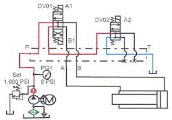
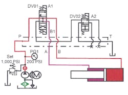
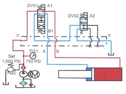
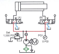
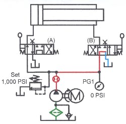
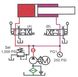
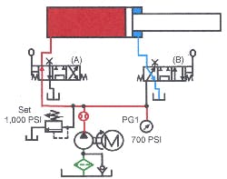
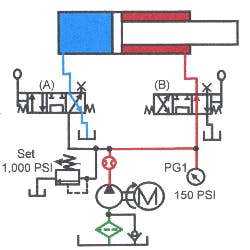
Figures 17-57 through 17-62 show a manually operated regeneration circuit using a pair of lever-controlled directional valves. To make the cylinder move with this circuit, the operator must have both hands on the levers. Regeneration takes place when the operator shifts the valves as explained below.
Figures 17-58 and 17-59 show how the circuit reacts when the operator shifts only one valve. Pump oil always has a path to tank through the idle valve so the cylinder does not move. Shifting one of the valves and then tying it down allows the cylinder to extend when the second valve is shifted. However, the cylinder cannot retract until the operator releases the tied-down valve, and shifts it to the retract position.
In Figure 17-60, the valves are shifted to extend the cylinder at regeneration speed. Valve sends pump oil to the cylinder’s cap end while valve B directs rod-end oil to mix with the pump flow. During this part of the stroke the cylinder extends at half force and double speed. The operator controls when the cylinder goes out of regeneration into slow speed and full force.
Figure 17-61 shows the valves shifted to give full thrust. Pump flow goes to the cylinder’s rod end and oil from the cap end goes directly to tank.
To use this circuit for the anti-tie down feature only, add a check valve in the pump line to valve B, The check valve allows pump flow to go to valve B, but blocks regenerating flow from the cylinder from going to the other manual valve.
