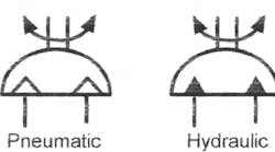
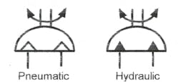
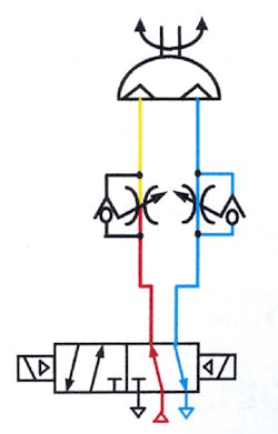
Some machine actions require rotary motion for only a portion of a turn. Using a hydraulic motor to perform a partial-turn function is expensive and it is difficult to accurately stop a motor at a specified degree of rotation. A clevis-mounted cylinder, attached to an arm and keyed to a shaft, produces rotary action, but is limited to 90° or less. At 90° rotation, a cylinder/lever arrangement has half torque or less when it starts and nears the end of stroke. To obtain partial- or multiple-turn rotary action and/or accurate stopping of rotary output, use one of the rotary actuators shown in this chapter. Figure 19-1 pictures the symbols for air- and hydraulic-operated rotary actuators.
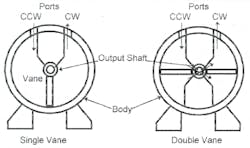
Figure 19-2 provides simplified cutaway views of vane-type rotary actuators. The figure depicts both single- and double-vane-types. The vanes attach to an output shaft and have seals around their periphery. When fluid pressure on a given vane area pushes it through the body cavity, the output shaft turns with a given torque. The maximum rotation of vane rotary actuators is limited to approximately 280° in a single-vane model and approximately 100° in the double-vane configuration.
A double-vane rotary actuator sends fluid to the push side of the opposite vane through drilled passages in the shaft, as shown by dashed lines and arrows. Pressurized fluid at the CW port turns the output shaft clockwise. Pressurized fluid at the CCW port turns the output shaft counterclockwise.
Most vane-type rotary actuators operate at lower pressure and torque limits of 2500 to 5000 in. lb. Some manufacturers do make units that operate at up to 3000 psi, with torque in excess of 700,000 in. lb.
Vane-type rotary actuators have no effective way of internally cushioning or limiting the degree of rotation. An external method must be used to limit rotation or cushion the load. Some manufacturers offer a valve and stroke-limiting package that makes rotation degrees adjustable and gives variable deceleration and cushioning. Check manufacturers’ catalogs for more information on these packages.
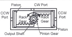
Figure 19-3 illustrates one design of a rack-and-pinion type rotary actuator. This cutaway view shows a double-rack design that has fluid in the area where the pinion runs. This configuration requires a high-pressure shaft seal but assures that the rack and pinion is well lubricated. With fluid piped to the CW port, the output shaft turns clockwise. With fluid piped to the CCW port, the output shaft turns counterclockwise. This design works best in pneumatic or low-pressure hydraulic applications. The torque range usually does not exceed 2500 to 3500 in. lb.
The cutaway view in Figure 19-4 shows another style rack-and-pinion type rotary actuator. This design has opposing pistons with a rack gear as the piston rod. Fluid only enters the blind side of the piston so the pinion shaft never sees pressure. When fluid enters one of the piston cavities, that piston moves, pushing the rack gear to drive the pinion, and producing rotary output. With fluid piped to the CW port, the output shaft turns clockwise. With fluid piped to the CCW port, the output shaft turns counterclockwise.
The rack-and-pinion design rotary actuators shown in Figure 19-4 are available with a second rack gear and pistons mounted on the opposite side of the pinion. This double-piston setup produces twice the torque in both directions of rotation.
Optional stroke limiters select a precise stopping point at any degree of rotation less than maximum. Also available are cushions that decelerate rotation speed near the end of the stroke. Cushions are adjustable and not affected by the stroke limiter option in the same rotary actuator. This type rotary actuator is available with an optional hollow output shaft.
Rack-and-pinion rotary actuators operate equally well on pneumatic or hydraulic pressure (up to 3000 psi). They generate torque up to 200,000 in. lb for air service, and up to 15,000,000 in. lb and higher for hydraulic service. Output shafts turn any number of degrees up to five rotations according to piston and rack gear size.
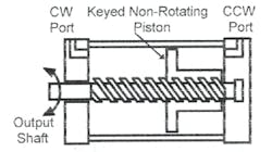
Figure 19-5 shows a simplified cutaway view of a spiral-shaft rotary actuator. (There are several variations of spiral-type rotary actuators, but all function similar to this diagram.) The spiral-shaft rotary actuator has a keyed, non-rotating piston with a hollow rod. The hollow rod has a set of internal spiral grooves that mesh with the spiral shaft. The spiral-grooved shaft only has rotational movement and extends through the housing as an output shaft. With fluid piped to the CW port, the output shaft turns clockwise. With fluid piped to the CCW port, the output shaft turns counterclockwise.
One available option is a stroke limiter that allows a precise stopping at any degree less than maximum. Also available are cushions to decelerate rotation speed near the end of stroke. Some manufacturers make this type rotary actuator with an integral cylinder that adds linear movement to the output shaft.
The spiral-shaft rotary actuators in Figure 19-5 operate equally well on air or hydraulic power. They operate at pressures up to 3000 psi and produce torque up to 20,000 in. lb for air service, and up to 5,000,000 in. lb for hydraulic service. Output shafts normally rotate 360° with more turns available on special order.
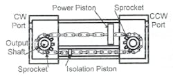
Figure 19-6 shows a simplified cutaway view of a chain-and-sprocket rotary actuator. It consists of a large-diameter power piston with a roller chain attached to both sides. The roller chains go around a sprocket at both ends and attach to both sides of a smaller isolation piston. When pressurized fluid enters a port, it pushes against both pistons with equal force. Because the power piston has more area, it moves away from incoming fluid. The smaller isolation piston regenerates into the incoming pump flow. (To find the effective working area, subtract the area of the isolation piston from the area of the power piston.) With fluid piped to the CW port, the output shaft turns clockwise. With fluid piped to the CCW port, the output shaft turns counterclockwise.
Moving a load rapidly without shock
Raising a well-guided table 24 in. in 1.5 sec; then, after removing a part, lowering it in 1 sec is a challenge. The part cannot stand high starting forces and must stay on the table at the end of stroke.
The schematic and pictorial layout in Figures 19-7 and 19-8 shows a way to move something -- such as a lift table -- through a fixed travel rapidly, with little shock. (For other ways to move this type load, using a straight cylinder, see Chapter 14.) The action here is similar to a crankshaft-type press, where the platen and tooling move rapidly and smoothly from top dead center, through bottom dead center, and back with little or no shock.
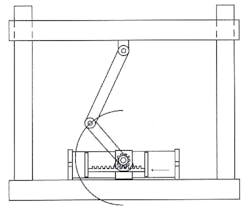
The layout in Figure 19-7 shows a hydraulic rotary actuator with a 6-in. arm attached to the output shaft. For a large table, choose a rack-and-pinion actuator with a through shaft and put an arm on both sides. Attach the 6-in. arms with pivot pins to 12-in. arms that also connect to the table with pivot pins.
Porting fluid to the right end of the rotary actuator makes the piston drive the rack gear, thus turning the pinion. The pinion starts at low torque and accelerates quickly. As the pinion turns, the table moves up -- slowly at first and then constantly gains speed until mid stroke. From mid stroke on, the table decelerates and actually stops just as the rotary actuator finishes its stroke. The action is fast and smooth without jerks. There is no need for position indicators, shock absorbers, or other devices to position the table. Use a rotary actuator with cushions to minimize shock.
Even though this is a running-away load on the return stroke, motion remains smooth. The schematic drawing in Figure 19-8 shows a counterbalance valve in the lowering line to produce hydraulic resistance that offsets the table and/or part weight. Set the counterbalance valve high enough to offset the weight and stop free fall. Setting the counterbalance valve too high uses excess energy, resulting in unnecessary oil heating.
If the load is resistive part way and running away the rest of the stroke, use a counterbalance valve with an external and internal pilot. The counterbalance valve in Figure 19-8, with internal piloting only, adds extra resistance even with a resistive load. This might cause the circuit to operate at higher pressure than needed and possibly stall. (See Figures 19-20-23, for a full explanation of a resistive, overrunning load circuit.)
With a 360° rotary actuator, action is like the cycle of a crankshaft-type press. For each direction the rotary actuator strokes, the table completes a lift or lower motion. This same mechanism and circuit can move a horizontal load with the same results
Some typical applications for rotary actuators
Figure 19-9 shows a I80° turnover station powered by a rotary actuator. The shaft of the turnover attaches directly to the actuator shaft without gearing or other devices. Because the load is resistive part way and running away for the rest of the stroke, use an internally and externally piloted counterbalance valve for good control. If speed is the same for the whole stroke, use a meter-out flow control in place of the counterbalance valve in a hydraulic circuit.
The clamping device in Figure 19-10 allows the part to be loaded from the top without interference. This is an advantage for some machining operations. Calculate the downward force of the clamp arm by dividing its length into the torque of the output shaft. When using a 180° rotary actuator, the clamp arm is completely out of the way for loading.
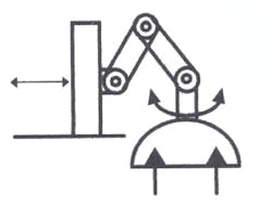
The toggle arms in Figure 19-11 rapidly move a platen to and from the workstation. The arms also multiply the force as they reach the work and get into a straight line. This mechanism only works when the closed height does not change for a given setup.
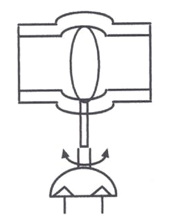
Many 90°-turn rotary actuators operate butterfly or ball valves at remote locations, as in Figure 19-12. With adjustable stops or control valve circuits, these actuators give partial movement to control product flow.
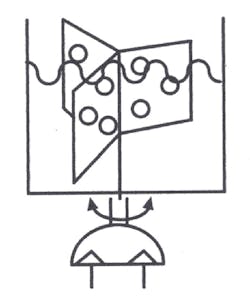
For an agitator drive, especially in an explosive atmosphere, use the rotary actuator setup shown in Figure 19-13. Select an air pilot-operated pneumatic or hydraulic directional valve and pneumatic limit valves to cycle the unit for explosion-proof applications.
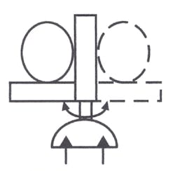
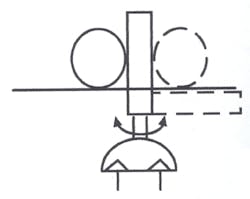
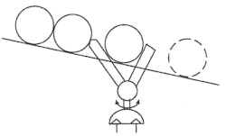
The swinging stop in Figure 19-14 holds parts on a conveyor while they stack up to a specified number. When the required parts have accumulated, the actuator swings the stop out of the way to let them pass.
Figure 19-15 shows a single-part release. As the rotary actuator swings through approximately 90°, it releases one part while holding back all others.
There are many applications where rotary actuators save time and cost over other fluid power devices. They are often not as expensive as the components they replace, and they reduce maintenance costs for the life of the machine.
More circuits for rotary actuators
To control rotary actuators consider all of the hydraulic-motor circuits in Chapter 12. Many cylinder circuits work well also, but a rotary actuator has the advantage of equal areas in both directions of travel. Note that these equal areas make it impossible to use a conventional regeneration circuit, but the flow-divider regeneration circuits shown in Chapter11 work well.
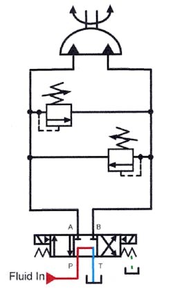
The circuit in Figure 19-16 shows a rotary actuator with cross-port relief valves to protect it from excess pressure when the valve centers with ports A and B blocked. If the rotary actuator has an overrunning load, sudden stops cause damaging pressure spikes. The dual cross-port relief valve shown in this example allows the actuator to decelerate quickly, without shock and its resulting damage.
Set the cross-port relief valves pressure so that it is equal to or higher than the system relief or pump-compensator setting. A pressure setting equal to the system relief valve gives a stopping distance equal to the distance it takes to accelerate the load. Higher pressure settings stop the load in less distance. Always set cross-port relief valve pressure lower than the actuator's maximum operating pressure.
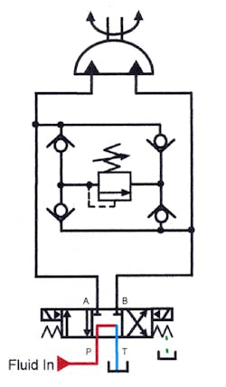
In Figure 19-17, a single relief valve with four check valves gives the same cross-port relief function without having to make two adjustments. Otherwise, this circuit works the same as the one in Figure 19-16.
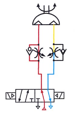
Flow control circuits shown in Figures 19-18 and 19-19 control the speed of the rotary actuator. All of the advantages and disadvantages of the different flow control circuits apply here as well as to cylinders. (See Chapter 10 on flow controls for the ways to control an actuator's speed.)
Resistive to over-running load application
In Figure 19-20, a turnover table driven by a rotary actuator starts off as a resistive load and goes to over-running at about mid stroke. This is not an unusual application for a rotary actuator. When speed of rotation is the same for the whole stroke, use a meter-out flow control circuit for this application. When using variable speed such as fast traverse and slowdown, use the counterbalance circuit shown and described.
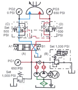
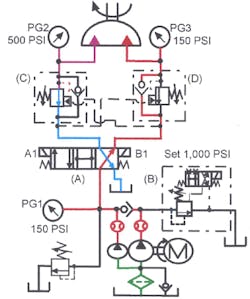
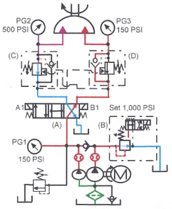
To make it possible to keep pressure high enough to move the load and also have a slow down at the end of travel, use the circuit shown in Figures 19-21 through 19-23. This circuit has both a high-volume pump and a low-volume pump for fast travel, but uses only the low-volume pump for slow speed. Normally open solenoid operated relief valve B unloads the high-volume pump near the end of the stroke. Counterbalance valves C and D slow the actuator when the high-volume pump unloads.
In Figure 19-21, both pumps lift the load rapidly. Energizing the solenoid on normally open solenoid-operated relief valve B and solenoid B1 on directional valve A sends flow from both pumps to the actuator. Fluid from both pumps raises the load through the resistive part of the cycle. (Note that gauges PG1 and PG3 indicate 650 psi.) The external pilot port of counterbalance valve C in the outlet line of the actuator senses that working pressure, causing it to open fully. Pressure at gauge PG2 shows 0-psi backpressure in the outlet line of the actuator, so there is no wasted energy. As long as the rotary actuator lifts the load, external pilot pressure keeps counterbalance valve C open, allowing free flow to tank.
When the load goes over center, as in Figure 19-22, the rotary actuator tries to run away. When this happens, external pilot pressure to counterbalance valve C drops and it tries to close. When the counterbalance valve closes enough to restrict movement of the actuator, pressure at its inlet increases. The pressure increase is partially from the over-running load while the rest is from the pump pushing on the other side of the actuator piston. As the load goes over center and continues on, pressure at PG2 steadily increases while pressure at PG3 decreases. With a counterbalance valve creating resistance, it takes pump flow and its resulting pressure to keep the rotary actuator moving. Speed is as fast as pump flow dictates.
In Figure 19-23, the solenoid on normally open solenoid-operated relief valve B is deenergized near the end of the stroke. This unloads the high-volume pump at low pressure. Decreased flow to the actuator causes a pressure drop at its inlet and outlet. Counterbalance valve C again tries to close, holding the load back until the low-volume pump starts pushing it at a slower rate. Slow down is quick and smooth. This circuit allows the turnover to move rapidly during most of the cycle, while the slow down eliminates shock at stopping.
The schematic diagram shows two counterbalance valves to handle a load in each direction. If the carrier returns without a load, set counterbalance D lower, to reduce the energy requirement on the return stroke.
