Slip-in cartridge directional valves (continued)
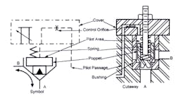
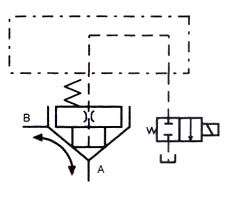
The symbol and cutaway for a slip-in cartridge valve in Figure 4-22 include a stroke-adjusting screw that limits poppet travel. Restricting flow by limiting poppet movement controls the actuator’s maximum speed. The filled triangle in the poppet symbol shows the skirted or modified poppet that allows smooth flow change as it shifts.
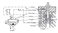
The cutaway in Figure 4-23 shows one design of a slip-in cartridge with a stroke limiter. The cartridge function is identical to any 1:2-ratio poppet except for the limited movement. Restricting the poppet movement makes the cartridge function as a flow control as well as a directional valve.
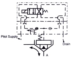
Figure 4-24 shows the symbol for an adjustable-stroke cartridge valve with a directional control valve cover. This particular valve only comes in a single-solenoid configuration as shown. Also, it cannot pilot other cartridge valves in the manifold. (Figures 4-27 and 4-28 show an adjustable stroke-cartridge in a circuit. These examples also show a problem that can occur when using a stroke limiter as a flow control in a meter-out circuit.)
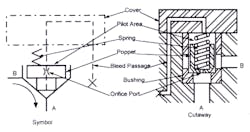
Figure 4-25 shows the symbol and cutaway for an internal-poppet, orifice-type cartridge valve. The internal poppet orifice supplies pilot oil from the A port only. Standard orifices that meet most needs are available. The internal pilot supply cartridge valve provides a check-valve function without drilling pilot passages in the manifold. As a check valve, it always allows free flow from the B port to the A port and blocks flow from the A port to the B port.
The 2-way cartridge shut-off valve in Figure 4-26 is for high flow systems. This 2-way shut-off might allow pump flow to a circuit as shown in the schematic. Also use a 2-way shut-off to let fluid flow from a large cylinder to tank for rapid advance. Using a normally open solenoid valve in place of the normally closed one shown allows flow through the cartridge valve until the solenoid is energized.
One advantage of the internal-pilot-supply-type cartridge valve is that it is not necessary to keep the pump running to have pilot pressure. This can eliminate a shuttle valve when an over-running load tries to move the cylinder.
The internally piloted slip-in cartridge always controls flow from the A port to the B port. Fluid is free to flow from the B port to the A port because pilot supply comes only from the A port.
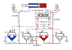
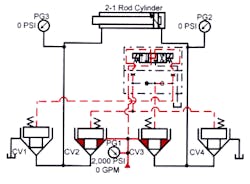
When using a stroke-adjusted poppet to meter-out flow from a cylinder with an oversize piston rod, look out for the problem that appears in Figure 4-27. This circuit pictures a horizontal cylinder with a 2:1 rod that needs a meter-out flow control. This is good circuit design for spool-type valves, but when using an adjustable-stroke slip-in cartridge valve, it can cause trouble. This circuit can actually increase the cylinder speed when making an adjustment to slow it.
The circuit in Figure 4-27 shows the valves shifted to extend the cylinder. Flow from the pump is passing through CV3 to the cylinder’s cap end. Oil from the cylinder’s rod end is flowing to tank freely through CV1 because the stroke adjuster is fully open. Pressure gauge PG1 shows a system pressure of 700 psi. Gauge PG2 in the cylinder’s cap line reads 700 psi, and PG3 at the cylinder’s rod line reads 0 psi. The 700-psi reading is from the load’s resistance (the cylinder is moving with no flow restriction). Pilot pressure is always the same as system pressure. Flow to the cylinder’s cap end is 50 gpm and flow from the rod end to tank is 25 gpm.
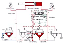
With the stroke limiter screwed in to restrict tank flow to 12.5 gpm, the conditions shown in Figure 4-28 will prevail. In a normal meter-out circuit with a flow control and a spool-type directional valve, the cylinder speed slows and system pressure increases.
With a cartridge-valve circuit, however, restricting flow from the cylinder’s rod end increases system pressure. Gauges PG1 and PG2 register approximately 1600 psi -- or a little more than twice the non-restricted flow pressure. This is because the load now is being moved by pressure on half the piston area in a regeneration circuit. Gauge PG3, at the cylinder’s rod end, climbs to approximately 1800 psi due to area-ratio intensification.
This intensified pressure acts on the half A port area at CV2, while half the B port area sees system pressure. Pilot pressure on the full pilot area of CV2 is 1600 psi, plus a spring force of, say, 75 psi. If the full pilot area is one square inch, the poppet has a closing force of 1675 lb. The 800-lb opening force on the poppet is generated by 1600 psi on half the area. The opening force on the other half area of the poppet is 900 pounds (1800 psi X 1/2 sq. in.), making the total opening force 1700 lb. With 1700-lb opening force and 1675-lb closing force, the poppet opens to allow rod-end oil to regenerate to the cap end. Instead of the cylinder slowing to half speed, it moves 150% faster due to regeneration. The more the flow from CV1 to tank decreases, the faster the cylinder extends. Note that restricting flow at CV3 as a meter-in flow-control circuit would allow infinite control of cylinder speed. Another option would be to use a shuttle cover and take pilot pressure from the pump or the cylinder’s rod end. As pressure intensified at the rod end, pilot pressure to CV2 would increase also.
Slip-in cartridge directional valves compared to spool-type 4-way directional valves
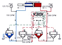
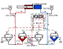
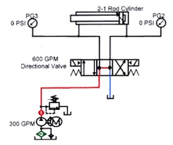
Figure 4-29 pictures a circuit with a 300-gpm pump powering a large-bore, 2:1 rod-diameter cylinder. This is the type of circuit that uses an important feature of slip-in cartridge valves. Flow from the rod end is only 150 gpm as the cylinder extends, but while retracting, flow from the cap end is 600 gpm. A conventional 4-way valve to operate the cylinder in Figure 4-32 must be capable of 600-gpm flow. A 4-way valve with this capacity is large and expensive. Its delivery may involve a long lead time.
Four slip-in cartridge valves can duplicate the function of the 600 gpm 4-way valve. This may sound expensive and inefficient, but with a circuit such as the one in Figure 4-29, it actually is more efficient, less expensive, and saves space.
The cylinder is extending in Figure 4-30, with 300 gpm going to the cap end through CV3. Simultaneously, the rod end of the cylinder is discharging 150 gpm to tank through CV1. With this difference in flow, it costs less and saves space to use cartridges of different sizes. Size the cartridges for nominal pressure drop at their maximum flow.
The cylinder is retracting in Figure 4-31. Flow to the rod end is 300 gpm while flow from the cap end is 600 gpm. For this higher cap-end flow, use a larger cartridge to minimize backpressure. This circuit will have three different-sized cartridges to carry the flow required during each phase of the cycle. Size CV1 for 150 gpm, CV4 for 600 gpm, and CV2 and CV3 for 300 gpm. When using a regeneration circuit, size CV3 for 600-gpm flow also.
The small amount of space taken by the cartridges, plus the lower cost and better availability of the parts make this system superior to one with a spool-type 4-way valve for high flows.
Another advantage of slip-in-type cartridge valves is their short response time. Cartridge poppets do not have land overlaps like spool valves have. Without land overlap there is flow when pilot pressure drops. Also, when the poppet opens, it only moves far enough to allow system flow to pass. When applying pilot pressure again, the poppet closes quickly without the extra travel often seen in spool valves. A spool valve, without stroke limiters, shifts full stroke. This full shifting may be far enough to pass several times the flow required. Then, when the spool starts returning to center, there is extra spool travel just to get back to controlling flow. This does not sound like much but faster response of cartridge valves can shorten cycle time and increase production.
The circuit in Figures 4-29 to 4-32 uses only one pilot control valve. This limits the versatility of the slip-in cartridges. Multiple pilot control valves, shown in the following circuits, make the use of cartridge valves even more attractive.
Slip-in cartridge directional valves on running-away loads
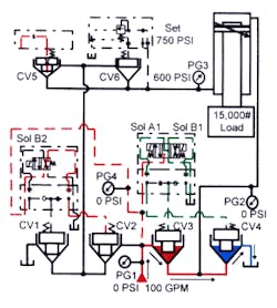
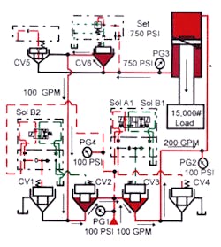
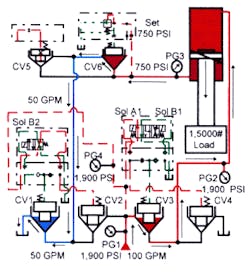
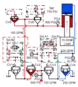
Figures 4-33 to 4-36 show a vertically mounted (rod down) cylinder holding a heavy platen and tooling. This cylinder will run away if oil discharges to tank uncontrolled.
A pressure-control cover (that makes CV6 a counterbalance valve) prevents rapid flow to tank. Cartridges CV1 through CV4 control cylinder flow and direction, and solenoid-operated directional valves shift their positions. Cartridge check valve CV5 bypasses normally closed counterbalance valve CV6 to retract the cylinder. With all solenoids deenergized, the pump unloads to tank through cartridge valves CV3 and CV4. Counterbalance valve CV6 keeps the load from falling at this time.
Figure 4-34 shows valve positions and likely pressures as the cylinder is regenerating forward. Energizing solenoids A1 and B2 closes CV4 and opens CV3, porting pump flow to the cylinder. This action also opens CV2 to allow cylinder’s rod end flow to go through CV3, combine with pump flow, and regenerate the cylinder forward. Counterbalance valve CV6 keeps the forward motion of the cylinder from going faster than the pump and regeneration volume as indicated by the 750 psi seen on gauge PG3. The cylinder is extending rapidly at low or no force.
As the cylinder extends, it makes a limit switch to deenergize solenoid B2. When solenoid B2 drops out, Figure 4-35, pilot pressure closes CV2, while CV1 opens to tank. The cylinder slows to about half the regeneration speed, but is now able to generate full force. Counterbalance CV6 still keeps the cylinder from free-falling as it approaches the work. When the cylinder starts to form a part, pressure increases to whatever it takes to do the work. The cylinder continues extending until it finishes the work stroke.
To retract the cylinder, the valve conditions shown in Figure 4-36 prevail. Energizing solenoids B1 and B2 allows CV2 and CV4 to open, and closes CV1 and CV3. Pump flow now goes to the cylinder’s rod end through cartridge check valve CV5. That bypasses normally closed counterbalance valve CV6. Oil from the cylinder’s cap end goes to tank through cartridge valve CV4.
Anytime all solenoids are deenergized, the cylinder stops and holds position. Counterbalance valve CV6 holds the cylinder in place as long as its pressure setting is greater than the load-induced pressure in the cylinder’s rod end.
When sizing the counterbalance valve, be sure to consider the cylinder’s static pressure. Slip-in cartridge valves have high flow capacity at nominal pressure drops. When available pressure drop is high, flow can increase to a point that the counterbalance valve’s response is too slow to stop the cylinder quickly.
Slip-in cartridge directional valves with prefill valves
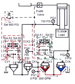
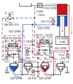
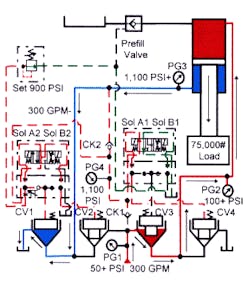
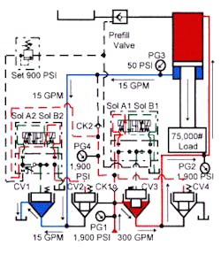
Figures 4-37 to 4-40 shows cartridge valves controlling a 50-in. cylinder with a 48.75-in. piston rod.
In Figure 4-37 the circuit is at rest with all solenoid valves deenergized. The cylinder maintains its position because load-induced pressure on the CV1 and CV2 pilot areas holds them closed. Pilot pressure reaches the pilot valves through CK1, while CK2 blocks flow to tank. When system pressure is higher than pressure in the cylinder’s rod end, CK2 lets this higher pressure into the pilot circuit. The pump unloads to tank through CV3 and CV4.
The size of CV1 is important, because controlling flow through it sets the cylinder free-fall speed. Size the valve for the pressure drop generated by load-induced pressure. A stroke limiter in CV1 actually sets maximum cylinder extension speed.
Energizing solenoid A1 shifts CV4 closed to block tank flow and leaves CV3 open to send pump flow to the cylinder’s cap end. Figure 4-38 shows the cylinder in a controlled free fall. Energizing solenoid B2 lets CV1 open, while holding CV2 closed. Oil from the cylinder’s rod end now has a path to tank through CV1.
A prefill valve lets oil from the tank into the cylinder’s cap end. The cylinder will advance as fast as the stroke limiter on CV1 allows. Free-fall speed can be in excess of 15 in./sec.
As the cylinder extends in free fall, it contacts a limit switch that de-energizes solenoid B2, Figure 4-39. CV2 remains closed and CV1 tries to close. As CV1 is closing, backpressure on the cylinder’s rod end will build to 900 psi and the pressure control will keep CV1 from fully closing. Because CV1 is restricting flow at 900 psi, the cylinder decelerates and tries to stop. While the cylinder is slowing, decreased vacuum in the cap end lets the pre-fill valve close. After the prefill closes, pump flow forces the cylinder to keep moving and rod-end pressure keeps the pressure control on CV1 open. Deceleration is smooth and rapid. The cylinder continues extending toward the work at the slower pump rate.
Figure 4-40 shows the cylinder at work. Solenoid A1 is still energized and solenoid B2 has been energized again. (Solenoid B2 could be reenergized by a limit switch or by a pressure switch when the cylinder contacts the work.) Energizing solenoid B2 lets CV1 open fully, taking away the 900-psi backpressure that decreases tonnage. The cylinder extends at the force required to do the work (up to relief pressure setting).
To retract the cylinder, energize solenoids A2 and B1. Solenoid B2 closes CV3, pilots the pre-fill valve open, and opens CV4 to tank. Solenoid A2 closes CV1 and opens CV2, sending pump flow to the cylinder’s rod end. The cylinder retracts rapidly with most of the cap-end flow going to tank through the pre-fill valve. In case of power failure or emergency stop, the cylinder stays where it is, or if it is moving, it decelerates, stops, and holds its position.
