Oversize rod cylinders
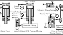
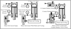
Cylinders with oversize rods can end up with dangerously high intensification pressures under certain conditions. The cutaway in Figure 15-17 shows a cylinder mounted vertically with its rod down. The rod area is approximately half the piston area so the annulus area around the rod is also approximately half the area of the piston. The left circuit shows the cylinder extending with a meter-out flow control circuit. For the 5-in. bore cylinder with a 3 1/2-in. rod and the pump compensator set at 3000 psi, pressure in the rod end would be approximately 5880 psi as the cylinder approaches the work. If this is a hydraulic press, middle circuit, with 5000 lb of platen, tooling a load-induced pressure of 499 psi would bring the rod end pressure to 6379 psi. This much pressure could damage the cylinder seals, over-pressure the flow control, and exceed the rating of pipe connections.
The circuit on the right eliminates all of the above problems but still allows speed control of the cylinder. A counterbalance valve on the cylinder rod end set at 100 to 150 psi above load-induced pressure would keep the platen from falling while at rest or while it is approaching the work. A meter-in flow control sets cylinder speed and as fluid enters it, pressure in the cap end only rises to approximately half the counterbalance valve setting. The cylinder starts extending when pressure in the rod end reaches approximately 574 psi, which is well below the rating of all components.
Each of the circuits in Figure 15-17 would control cylinder speed but the counterbalance circuit is the best choice for the reasons given plus it has a lot less energy loss.
Another reason for using an oversize rod is for regeneration circuits like the ones in Figure 15-18. Any single rod cylinder will at least attempt to extend with equal pressure at both ports and this is called regeneration. Whether it actually extends depends on the load it must overcome, maximum system pressure available, and what the rod diameter is. This is because the maximum force during regeneration is pressure times the area of the rod. The piston is in balance during regeneration and serves no function during the process.
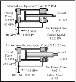
The standard rod cylinder in Figure 15-18 would extend at the rate of 12.25 in./sec at a maximum force of 3142 lb. Even if this is ample force to extend the present load, the amount of flow in regeneration is excessive. As the cylinder is regenerating forward with flow of 10 gpm from the pump, there would be 52 gpm coming from the head end for a total of 62 gpm to enter the cap port. This high flow would cause excessive back pressure and keep cylinder speed slow because the circuit relief valve would be bypassing at system pressure.
Another reason using a standard rod cylinder is not good practice is that its retract speed would only be 2.33 in./sec, so overall cycle time would not increase as much as first thought.
The above scenario is the prime reason for using 2:1 rod area ratios for regeneration. The lower cylinder in Figure 15-18 is the same bore but has a 31/2 in. oversize rod. This rod is not exactly 2:1 area ratio because it uses NFPA standard sizes for interchangeability. All NFPA cylinders have the largest standard rod that is up to but not over 2:1 area ratio.
The figures for the 2:1 ratio rod now show a net force on extend of 9621 lb. at a speed of 4 in./sec. During regeneration, flow from the head end is 10.4 gpm with a total flow to the cylinder of 20.4 gpm. This is a good measure of force and a reasonable flow rate that usually overcomes work resistance at easy-to-handle flow rates.
Retract speed would be 3.8 in./sec, making extend and retract speeds almost equal. When the rod diameter is exactly 2:1, extend and retract speed and force are identical -- the same as a double rod-end cylinder. However, getting exactly 2:1 area ratios requires an odd size bore or rod that may require special seals.
The circuits in Figure 15-19 show some standard regeneration setups used for particular needs. The full-time regeneration is a replacement for a double rod-end cylinder circuit. With a 2:1 area ratio rod, it will have identical speed and force in both directions. Even with standard rod diameter cylinders, force and speed are within 10% to 12% of the same, which is often satisfactory.
The full force at pressure buildup example uses a sequence valve to indicate work resistance and direct head-end oil to tank. A check valve in the regeneration flow line allows regeneration flow to the cap end and prevents pump flow to tank during the full force portion of the cycle. This circuit extends fast until work contacts, no matter the size of the part.
The full force at limit switch circuit uses a normally closed two-way directional control valve to send head-end flow to tank when a limit switch is made. This cuts cylinder speed in half so part contact is less abrupt. This circuit protects tooling, allows more time for visual inspection of alignment, and can give an operator more time to respond to unsafe conditions.
The circuits in Figure 15-19 may need a counterbalance valve to retard running-away conditions when the cylinders are vertically mounted. When this is necessary, the counterbalance valve must be externally drained to eliminate backpressure in the pressure adjustment chamber.
Adding a bleed-off flow control to the line between the head-end port and the check valve and after a counterbalance valve allows cylinder speed reduction when required. For complete coverage of regeneration circuits see the author’s upcoming e-book Fluid Power Circuits Explained.
Rotary output actuators
Air and hydraulic motors also are other types of actuators that turn fluid power energy into rotary output. They are pumps in reverse and can come in as many varieties. Unlike cylinders that are rated in pounds force thrust, motors produce twisting or torque that turns a shaft. Motors are rated in torque output usually stated in pound-inch (lb-in.), pound-foot (lb-ft.) American; or Newton-meters, (N-m) Metric.
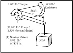
The example in Figure 15-20 shows how torque is measured and applied to shafts. With a 500-lb weight hanging from the end of a 2-ft arm rigidly attached to a shaft, the shaft would have to resist 1000 lb-ft of torque (500 lb X 2 ft) to keep from turning. This is only true when the weight is at right angles to the shaft. Changing arm length or the amount of weight changes the amount of torque. As noted in the example, the metric figure is in Newton-meters and one Newton-meter equals 8.851 lb-in. and 0.7375 lb-ft.
Why use a fluid motor?
The main reason cited for using air or hydraulic motors is that they have high torque in a small package. Air drills of 1/2 to 3 hp for many rotation speeds and torqus require less than one-third of the space a comparable electric motor setup would use. This means space at the work is less cluttered and/or more units can be applied. Hydraulic motors are even more compact especially in higher horsepower units. The main reason for the small size is no reduction gearing is required for hydraulic motors and small planetary units work well with air motors.
- Other reasons for choosing fluid motors are:
- They have instant or almost instant reversing capabilities. Because these motors are so compact and have little inertia to overcome, they can reverse rotation quickly without damage. Some motors act as oscillators that never make a full revolution.
- Variable speed capabilities of fluid motors are simple and result in little change in torque when it is a low-speed/high-torque hydraulic motor. A change in flow with flow controls or variable volume pumps requires little sophistication when minor speed changes can be tolerated. Sophisticated servo controls allow speed changes and can maintain tight control at any speed.
- Overload protection is part of any fluid power system and motors have the same ability. When a motor circuit meets resistance it cannot overcome, it stalls and holds torque without damage to the circuit or machine. Fluid motors are capable of stalling for long periods without over heating or damaging themselves. There is some internal leakage while stalled but this can be minimized with the right motor selection.
- Another place where fluid motors shine is in wet or explosive atmospheres. These motors have no electrical input so they pose no threat from sparks or overheating. A hydraulic motor can operate underwater with bio-degradable fluids without any of the problems electric motors have in this application.
Pneumatic motors
Air motors are often very inefficient and with air compressor inefficiency added there is often no more than 20% utilization of input power. This high inefficiency is offset somewhat in most applications because the air motor only has to run while work is taking place. This could mean the air motor must start and stop often but this is not a problem for fluid motors.
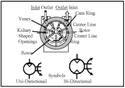
There are a variety of pneumatic motors in different configurations and with different attributes. The vane type shown in Figure 15-21 is one of the oldest designs. They are usually high to very high speed from 1000 to 30,000 rpm for everything from sanders and grinders to dentist drills. These motors may offer unidirectional or bidirectional rotation according to their design use.
The cutaway shows vanes in a rotor that is off center in a cam ring. Air at the inlet acts against the vanes halfway around, forcing the rotor to turn while spent air exhausts during the other half revolution. Only one vane in this unbalanced design is producing torque. The remaining vanes on the inlet side have pressure on both sides so they have no force.
The vane motor in Figure 15-21 is for medium-to-high-speed applications at low torque. Several manufacturers add reduction gears to give low-speed/high-torque capabilities.
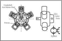
The radial piston motor in Figure 15-22 does not require reduction gearing for most low-speed/high-torque applications. Force from half the pistons is driving the crankshaft to turn it while the remaining pistons are exhausting. Inlet-outlet ports connected to a rotary valve driven by the crankshaft send 40 to 100 psi air through cored holes in the body and cylinder bores to and from the pistons. Most radial piston air motors run at less than 500 rpm due to air energy waste at faster speeds. These motors can be physically large and take a lot of mounting space. Some manufacturers make axial or in-line piston motors while a few have experimented with gerotor designs.
Hydraulic motors
Hydraulic motors come in the same variety as pumps. Many are low-speed/high-torque, some are high-speed/low-torque, and a few are low- or high-speed/high-torque. The main difference between pumps and motors is that a motor is usually capable of having either port pressurized.
High-speed motors can reach 3000 rpm continuous to drive fans, lawn mower blades, and grinders. They usually do not have high torque starting capabilities but most applications they are used on do not require this feature. Low-speed/high-torque motors usually have 75% to 90% of their maximum torque to start. They usually operate at 500 rpm or less. Piston motors of the in-line and bent axis design have high low speed torque and can run at 1500 to 2500 rpm without losing efficiency.
Hydraulic gear motors
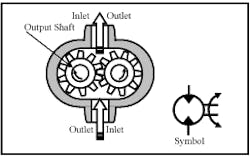
The gear motor shown in Figure 15-23 is one of the oldest designs and is built for high-speed/low-torque needs. At first it appears fluid entering the lower port pushes against two teeth to start the gears turning. However, a closer examination shows the left gear has fluid pushing on opposing teeth as it comes out of mesh and only the right gear has any twisting action. After one tooth of revolution, the left gear drives while the right gear is balanced and so on as the motor turns.
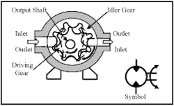
The high-speed gerotor motor in Figure 15-24 has similar characteristics to the gear-on-gear motor just mentioned. This is not a popular design but the gerotor concept with the idler gear held stationery shown next is made by many manufacturers and holds more than 50% of the small-to-medium high-torque/low-speed motor market.
The generated rotor hydraulic motor shown in Figure 15-25 is made high-torque/low-speed by holding the idler gear still and allowing the orbiting gerotor to cycle inside of it. This change causes the orbiting gerotor to make as many power strokes as it has teeth for every revolution of the output shaft. The seven-tooth gear shown makes seven power strokes while the output shaft turns once. A splined drive connection follows the orbiting gear and transmits the rotary motion to the output shaft.
Generated rotor motors give at or near full torque from about 25 rpm and normally do not go higher than 250 to 300 rpm. Maximum output torque is directly related to the width of the gerotor element which may be as narrow as 1/4 in. to 2 in. Pressure ratings as high as 4000 psi are common from most manufacturers.
Gerotor motors can have a selector valve that changes the internal rotary valve output to feed only half the chambers, causing the motor to run at twice the speed and half the torque. The gerotor design is machined with too close tolerances but must have some clearance to allow the inner gear to move. This makes it less efficient and as the gears wear, internal leakage increases. The geroler design has rolling seal points and can be setup much closer and has less wear for longer life. Most of the geroler types also use a plate valve which has less leakage and is wear compensating as well.
Hydraulic vane motors
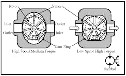
The hydraulic vane motor shown in Figure 15-26 is a very efficient design and works well for applications at 20 to 3000 rpm. Fluid entering one port pushes against two or four vanes as they extend in the cavities of the cam ring. Internal porting directs pressure and return fluid to the working and exhausting vanes. While half the vanes are being pushed by fluid, the other half are discharging spent oil to tank. The amount of torque is in direct relationship to the vane area exposed to pressure fluid and the distance the vanes are from shaft center. Speed is limited to how much displacement and what size ports the motor has.
The high-speed/medium-torque design with an elliptical cam ring gets full torque at approximately 100 rpm and can go as high as 3000 rpm. Because it covers such a broad speed range it is suitable for many applications where other designs fall short on torque or speed. The low-speed/high-torque design is designed for approximately 10 to 400 rpm and usually eliminates any need for gear reduction. Using a direct drive eliminates maintenance problems and makes a smaller package at the work area.
Hydraulic piston motors
The most efficient and versatile hydraulic motors are piston type but they are also the most expensive. Inline or axial and bent axis types operate smoothly from 10 to 2000 rpm with high torque throughout their speed range. Radial piston types go as low as 1 rpm but usually not higher than 400 rpm. Their main use is very high-torque/low-speed applications.
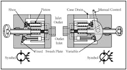
The cutaway in Figure 15-27 shows typical construction of inline fixed- and variable-displacement hydraulic motors. Low-displacement variable motors may be controlled manually while larger motors need pistons to change displacement. An inline hydraulic motor shaft rotates as fluid pushes against a piston, forcing its shoe to slide up the angled swash plate. A small amount of pressure fluid goes through an orifice in the piston and behind the shoe to keep it from rubbing metal-to-metal while it is producing torque.
With the swash plate at a steep angle, torque is high while speed is usually low. A shallow swash plate angle gives high speed but less torque. Most manufacturers recommend a minimum swash plate angle of 15° to 17° for best results. A maximum angle of 40° to 45° gives good torque and long motor life.
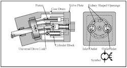
The bent-axis piston motor in Figure 15-28 has the same operating characteristics as the inline motor but is more rugged and capable of higher operating pressures. Since there is no sliding action of piston shoes there is less friction and higher torque for a given energy input. The angle of the cylinder block to the input shaft determines torque and speed ranges. The greater the angle, the higher the torque and the lower the speed. Kidney-shaped openings in both inline and bent-axis motors port fluid to and from pistons as they rotate. Internal leakage is sent to tank through the case drain. Variable-displacement bent-axis motors are available but not commonplace due to expense and size.
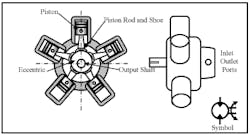
The radial piston motor shown in Figure 15-29 uses pistons pushing against an eccentric to produce rotary motion. These motors usually have five or seven pistons with rods and shoes, with half of them pushing against the eccentric while the other half return oil to tank. The shoes have high pressure fluid fed to them from the piston through the rod to keep them from rubbing the eccentric during the power stroke. A rotary valve attached to the output shaft feeds and exhausts fluid to and from the pistons as they turn the eccentric.
Some radial piston motors are made with a moveable eccentric that allows different offset amounts. Usually the offset is full or one-half so a motor with this feature can have higher speed at lower torque for fast movement. Eccentric-type radial piston motors are one type of motor that cannot function as a pump without special inlet considerations.
Other radial piston motor designs are similar in action and torque output, but arrange the pistons in different configurations. One design has the pistons facing in and pushing outward against a cam-shaped housing. The shaft is connected to the machine and the housing rotates. It was originally designed as a wheel motor.
Rotary actuators
When rotary output is one or two turns or less, a hydraulic motor could be used but repeat stopping accuracy could be a problem. There are several designs of rotary actuators that give rotary output for limited numbers of revolutions (usually under one revolution).
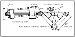
Figure 15-30 shows one way to achieve rotary action when the motion is 90° or less. A clevis-mounted cylinder attached to a lever arm that is driving a shaft gives no less than half the cylinder force times the lever arm length. In the example shown, torque on the shaft would be approximately 4000 lb-in. when the cylinder starts and finishes and approximately 6600 lb-in. when the angle between the cylinder and lever arm is 90°. Often maximum torque is only required at the end of stroke so arrange cylinder mounting to give the greatest torque at that point. Remember, retract force is less than extend force which could cause the cylinder to stall when reversed.
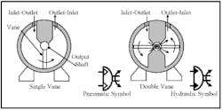
The vane-type rotary actuator in Figure 15-31 is a common design for both pneumatic and hydraulic fluids. The vane has seals around the edges where it contacts the housing to control leakage. Fluid entering from the left, as shown, pushes the vane away and forces fluid out the opposite port as it turns the output shaft. A single-vane rotary actuator is usually limited to 270° rotation or less. A double-vane rotary actuator usually only turns 90° or less. Torque is equal to the vane area times input pressure times the radius from the center of the output shaft to halfway across the vane. The symbol shows a semi-circle to indicate rotary action that is not capable of being continuous in either direction.
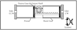
Another common rotary actuator is the single-cylinder rack-and-pinion rotary actuator shown in Figure 15-32. Several companies make these units in single- and dual-cylinder models with torque outputs up to and above 300,000 lb-ft. They can be pneumatic- or hydraulic-actuated. This rotary actuator design can turn more than one revolution because turns are in direct relation to pinion gear size and rack gear length. It may also be supplied with cushions, and/or stroke limiters for smooth adjustable stops. Fluid entering ports at the cylinder ends forces the piston to move away and drive the rack gear against the pinion gear. The pinion gear continues to rotate until the opposite piston bottoms out. Reversing flow to the pistons reverses output shaft rotation. Torque is equal to piston area times input pressure times the radius of the pinion gear.
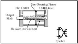
The helical gear rotary actuator shown in Figure 15-33 shows another design that can have more than one revolution of the output shaft. The number of rotations is in direct relation to gear teeth angle and the non-rotating piston stroke. Fluid entering and pushing against one side of the non-rotating piston forces it to move and impart the turning action to the output shaft through the helical gear and nut arrangement. This rotary actuator design is able to have deceleration built in and may be purchased as a double-shaft model.
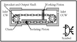
The chain-and-sprocket rotary actuator in Figure 15-34 depicts another way of achieving limited rotary output with more than one turn capability. The number of turns is in direct relation to the sprocket size and the working piston stroke. It can be used with pneumatic or hydraulic fluids. Fluid entering the CCW port pushes against the working piston and the isolating piston at the same pressure. Because the working piston has more area it will move left while the isolating piston moves right. The effective thrust is pressure times the area of the working piston minus pressure times the area of the isolating piston. The result of these calculations times the radius of the sprocket determines torque.
There are some other rotary actuator designs, but in most cases, they are variations of the ones presented here. For circuits using rotary actuators see the authors upcoming e-book Fluid Power Circuits Explained.
