Variable electrical transformers, often constructed as “auto-transformers,” are available from a number of manufacturers. They’re constructed much like that of a normal ferromagnetic, toroidal (donut-shaped) core as a single coil. Instead of a secondary winding, the outer layer of turns is devoid of insulation, and a wiper arm or slider arm is in rotational contact with the insulation-free outer layer of turns. The wiper arm, connected electrically to the output terminal, is rotated to adjust the amplitude of the output voltage.
Transformer Schematic
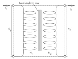
A two-winding transformer consists of two windings facing one another (Fig. 12). It operates with a common iron core, depicted as four parallel lines in the schematic (the number of lines isn’t standardized; two or more will suffice). Schematic convention doesn’t make it possible to indicate which winding has more turns, voltage/current ratings, or whether the transformer is step-up or step-down. Moreover, it can’t convey the number of loops and the actual number of turns on the transformer.
The primary and secondary “talk to each other” by means of the linking flux lines. Thanks to the self-induced and mutually induced voltages, the primary “knows” there’s an increase in the secondary load (more current) because of the change in its flux. When linking with the primary winding, it reduces the self-induced voltage in the primary, allowing more input current to deliver more power to the primary winding. It’s the electrical equivalent of a simple gear ratio; however, the transformer must be operated with ac power in and out.
Although the turns ratio defines the voltage ratio, it’s only an approximation. Because transformers inevitably suffer losses, as is the case with any type of power-transmission device, transformers are typically offered with a certain output voltage(s) at a certain input voltage. A few extra turns are added to compensate for the voltage loss.
For instance, normal ac line voltages are 120 V, 240 V, 440 V, and higher. Meanwhile, electronic circuits for controls often require much lower levels, normally 18 V down to even 3 V. The transformer is a perfect device for dropping the voltage to more usable levels.
This file type includes high resolution graphics and schematics when applicable.
Analogous Hydraulic Transformer
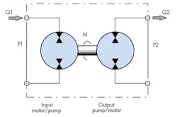
It’s possible to conjure a hydraulic analogy to the transformer, but it isn’t necessarily practical. Figure 13 shows such a machine in simplified schematic form. The input device is a universal pump/motor—it can accept hydraulic input power in the form of Q1 and P1, as well as supply output torque and speed through its output shaft.
In fact, that’s just how the input device is acting in the figure. The common mechanical shaft drives the input shaft to another universal pump/motor that’s acting as a pump. In turn, the shaft speed and torque are converted to pressure and flow in the form of P2 and Q2. Thus, the “hydraulic transformer” has hydraulic power in and hydraulic power out, like an electrical transformer that has electric power in and out.
The transformer function is best understood by inspecting the defining equations for the system. Assuming both machines are ideal, that is they have no losses (100% efficient):
P1×Q1 = P2×Q2
Because both machines are lossless, the input power equals the output power. Each machine has its own displacement, so the two flows can be replaced with their displacements. When speed, N, is measured in radians/second and the displacement in volume/radian, the result is:
P1 × D1 × N = P2 × D2 × N
From that equivalency, we derive:
P1/P2 = D2/D1 = Q2/Q1
The above three equations are identical to those for the electrical transformer, which leads to the analogy of the two machines. The displacement ratio, D2/D1, is analogous to the turns ratio of the electrical transformer. However, the analogy extends beyond the mathematically obvious—the incoming electrical power in volt-amperes converts to magnetic flux in the iron core, which changes the medium in the transformer.
In the hydraulic transformer, the medium is the conversion of hydraulic power, or pressure-flow product, into mechanical power in the form of the torque-speed product at the common shaft. Therefore, the torque and speed can be considered analogous to the flux and the mechanical shaft analogous to the electrical transformer’s iron core. Interested readers are encouraged to carry the analogies further, to any extent possible. The hydraulic transformer can, for example, intensify the pressure, but only with a concomitant de-intensification of flow to conserve energy.
Analogous Mechanical Transformer
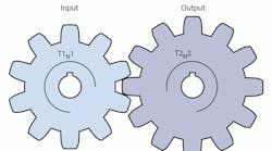
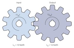
Although this series covers electric-hydraulic analogies, it would be a mistake to exclude the mechanical transformer due to its ubiquity and that it’s a part of both the electric and hydraulic technologies. The mechanical transformer simply consists of a pair of gears (Fig. 14). In the diagram, T = torque; N = rotational speed; and L = the number of lobes (or teeth) on each respective gear.
There are other purely mechanical transformer analogies; for instance, belts and pulleys and even conveyors can be characterized with a similar set of equations. To save space, those equation derivations aren't included here. Gear sets have not been made with variable ratios. Nonetheless, variable sheaves have shown success in making speed or torque ratios variable in some belt-pulley drive systems.
Magnetism, Flux Fields, and Transformers
In summary, looking back at Parts 5, 6, and this article, Part 7 of the series, it’s become clear that magnetism plays a vital role in the realm of electrohydraulic analogies for several reasons:
• Most important, magnetism, especially in the use of solenoids and electric motor prime movers, is important to the implementation and application of electrohydraulics.
• Hydraulics has no analogy to the hydraulic medium’s external fields. This fact is one of the major disconnects between the two energy transmission media. Fields that alter the region surrounding the electrical phenomena are unique to the electrical medium. It’s amazing that the existence of an isolated electrical particle or particles, such as a bunch of electrons, can be detected without so much as seeing the particles or even touching them—it’s sheer magic. And if those particles are sent into motion and create a current, it forms a new kind of field called the magnetic field. It’s relatively easy to detect, too. No one has the foggiest notion how, or even why, these fields exist. Nor do we know why they don’t exist around isolated fluid particles. We can measure them and put them to use for the betterment of mankind in ways that number in the millions, if not billions, of marvelous gadgets.
• A treatise on analogies must also point out where the analogies fail or don’t exist at all.
• A study of magnetism is an ideal subject for introducing the idea of hysteresis. Hysteresis isn’t just an electrical phenomenon; it occurs in mechanical parts in the form of backlash or stiction (stick-slip operation). Hysteresis also introduces the idea of memory, which is essential to effective digital machines and control of machinery by digital controller means.
• Electrostatic fields exist; however, they will only be discussed as the need arises in upcoming parts of this series. They are not as important to electrohydraulics as magnetic fields.
• Transformers will operate only on alternating current. Operation on direct current can cause transformers to burn up.
• Transformers, like all electromagnetic ac machines, are constructed with laminated cores to minimize core losses.
• Another key characteristic of transformers is that they allow for different grounds on the secondary relative to the primary circuits.
• Analogies to the electrical transformer exist in the purely mechanical realm as well, such as a simple gear set and a belt with pulleys.
• Mechanical transformers don’t require their inputs to be alternating—they transmit unidirectional motion quite well. Electrical transformers must absolutely be excited with ac. To power them otherwise would invite burning them up in the worst case, to simply not working in the best case.
