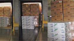
Recent product improvements by ETA Industries Inc., New Brighton, Pa., to the Rolflor Cargo Handling System (CHS) are reflected directly in the bottom line of their customers. Rolflor is a “live floor” conveyor built directly into tractor trailers used for short haul, quick-turn situations, where the fast load and unload of the trailer can result in substantial savings in both man hours and equipment use for the user.
Trailers incorporating the Rolflor CHS are typically used by suppliers to manufacturers using JIT strategies in production, or by a central warehouse servicing a network of local outlets — multiple Fortune 500 listed companies and the Defense Logistics Agency, for example. To achieve maximum return on investment, transit distance between locations will be short and time spent at either dock will be brief. Applications such as these are where the Rolflor really shine. A fully loaded 53-ft long trailer can be unloaded and ready for release from the dock in 4 min or less. For unloading, the entire load of cargo is pushed out of the trailer onto steel floor plates, which are required because concrete floors would not hold up to continuous wear. An alternative used by some firms is to have Rolflor unload directly onto their plant’s automated material handling system. Either way, the unloading does not require forklifts entering the trailer, saving needless wear and tear on the equipment.
Designed and built to order
As no two customers’ needs are exactly the same, each system is built to fit the demands of the application. However, any one customer might have two or more trailers fitted exactly the same. For instance, a bakery was leasing a fleet of ten trailers to transport loads of baked goods at its production facility to an offsite distribution center. The leased fleet was replaced by two Rolflor equipped trailers. Using the Rolflor semiautomatic indexing system when loading, the forklift operator places two stacked pallets on the left of the trailer, and another stacked pair beside it to the right. The load is then automatically indexed one pallet length into the trailer and stops; ready for the next row of pallets. The cycle is repeated until the trailer is fully loaded.
At the distribution center, each fully loaded trailer is backed to the dock door, plugged into dock power, and unloaded by the driver in about 4 min. The load is pushed out onto steel deck plates far enough into the building to allow closing the dock door behind it. At no time during loading or unloading is it necessary for a forklift to enter the trailer. In this particular instance, the two-trailer operation handles more than 100,000 pallets annually with payback from utilization of $190,000 from four fewer forklift operators on two shifts (approximately $160,000) plus savings of the leased equipment cost of $30,000 annually. Other examples can be found on the Rolflor website, at www.rolflor.com.
What it’s made of
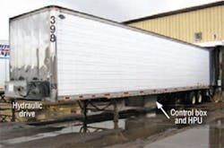
The Rolflor conveyor consists of front and rear drive subassemblies, each of which is housed in a rugged, welded steel enclosure. The enclosures are mounted at the front and rear of the trailer with a conveyor belt in between — a design reminiscent of casette audio tapes. The conveyor belt is not continuous, but, rather, is two belts. One end of each belt is attached to a drum at the front or rear of the trailer, and the other end of the belts are attached to each other. The narrower load puller belt is attached to the front drum and follows the wider as the trailer is unloaded. Thus, the front drive pulls the load into the trailer from the dock, and the rear drive (with the wider cargo floor belt) pushes the load out the back of the trailer.
A hydraulic power unit consisting of a totally enclosed fan-cooled threephase electric motor close-coupled to a hydraulic pump is installed on the undercarriage of the trailer. The HPU has 20-gal reservoir with filterbreather, level-temperature gauge, and clean-out door.
The two drive subassemblies consist of the hydraulic motors, gearboxes, and drums the belts wind on and off of. The rear assembly features a fiber-reinforced belt that is less than 3/16-in. thick. The upper (load) surface is coated with a special wear-resistant resin that has a high coefficient of friction against a wood pallet. The belt’s lower surface is made of polyester fabric impregnated with a wear and chemical resistant resin and low coefficient of friction against the trailer floor. The belt slides directly on the trailer floor and uses low-friction floor plates to further minimize the coefficient of friction to the load. The belt is about 92 in. wide and 3/16 in. thick, so no cargo space is sacrificed by the installation. Maximum loads of 30,000 to 55,000 lb can be accommodated by sizing the hydraulic components and the gearbox.
A typical installation has two identical operator stations — one for load and one for unload — mounted inside the dock doorway. A cable from the operator’s control panel plugs into the HPU on the trailer, placing load control on the dock where loading or unloading of the trailer can be observed. Electric power for the HPU is usually supplied by the dock, but it can be supplied by an optional diesel engine mounted within the hydraulic power unit. Electrohydraulics was chosen over an electromechanical drive due to the higher power density of hydraulics.
In control
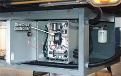
The electrohydraulic control system was designed and implemented by Steve Byers, Electronics Application Specialist, from Scott Industrial Systems, Dayton. A Divelbiss HEC- 2000-E-R controller was chosen to replace an earlier relay logic controller because of the ease of programming coupled with the broad operating temperature range of –40° to 80° C necessary for the application.
The HEC-2000-E-R accommodates eight digital inputs (8-32 Vdc) and eight digital outputs (8-32 Vdc up to 4 A). Two of the inputs may be used as inputs for high speed counting and all of the digital outputs are PWM capable. A CAN port supports SAE J1939 and OptiCAN. This solid state design allows for easy adjustment of variables, providing a far more responsive and precise system overall.
Mike Colgin is marketing manager at Divelbiss Corp., Fredericktown, Ohio. For more information, contact him at [email protected] or visit www.divelbiss.com.


