Slow and steady leaks in hydraulic systems can drain profits for industrial enterprises. Equipment leaks can result in costly downtime, increased fluid usage, and higher waste and maintenance costs.
Battling leakage is difficult because of the many hydraulic systems and potential leakage points in manufacturing facilities. Maintenance technicians need to be organized to deploy maintenance resources efficiently. Following are several key tips that can help you more effectively monitor and track equipment leakage and limit its negative impact on the bottom line.
Identify each system
To begin tracking, catalog all major hydraulic systems and assign them a registration number. The registration number will simplify recording of oil consumption. Also, measure or estimate oil capacity for each system.
Acceptable leakage rates are largely proportional to capacity. Label each reservoir with the correct fluid and assign a registration number. Include a bar code on the label for the registration ID to facilitate data collection.
It is important at this point to consider the project scope. Attempting to track every gallon used may overburden lubrication personnel and slow progress. Limit systems in the program to those that are likely to represent the most significant portion of leakage in the plant.
Typically, the largest hydraulic and circulating systems are most prone to leakage, so they should be monitored closely.
When it comes to hydraulic equipment, recognize that the majority of operational failures result from water or air contamination. It is essential to identify leakage points quickly to help minimize the chances that air, water, or other contaminants will enter the system and disrupt its operation and performance.
Install meters on filling devices
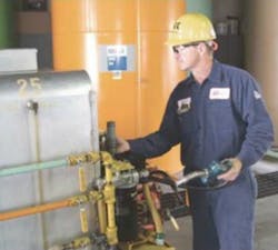
When beginning a leakage and monitoring program, maintenance personnel should install a flow meter to accurately measure the amount of lubricant added to a reservoir and limit its negative impact on the bottom line.
Flow meters are common lubricant dispensing mechanisms available from suppliers. As lubricant is dispensed, a flow meter tracks the amount of fluid that is dispensed on an analog or digital readout. This gives the operator a precise calculation of oil dispensed for each point requiring lubrication.
Measure and record results
Begin recording additions of oil to systems in the study. To ensure best results, track these three items:
• date and time,
• reservoir identification, and
• quantity of oil used.
Data collection is the most important step and requires the most work. An electronic data collection device, such as a personal digital assistant (PDA) can be used for this task. Many PDAs use a simple spreadsheet program.
More sophisticated devices incorporate barcode scanning to facilitate data entry.
A program would have the lubricator press a button to open a new record, scan the reservoir tag for the ID, and enter the quantity delivered. Data from the electronic device is downloaded to a computer for evaluation and reporting.
Determine baseline HFI
Consumption figures should be tracked to accurately evaluate each individual system and overall success. This also helps to prioritize repairs.
Develop a baseline consumption by considering the total annual consumption history or the first two months of data collection.
Next, determine the baseline hydraulic fluid index (HFI) to use as a standard to which your future calculations can be measured. The HFI is determined by dividing the annual usage of the reservoir capacity by its total capacity.
Sum of total reservoir capacity
An example calculation to figure HFI might be as follows: Your company has a hydraulic system with a total reservoir capacity of 100 gal. This represents the total system reservoir capacity. Suppose for this unit, your company uses an average of 300 gal of oil per year, representing the annual lubricant usage. The above calculation — dividing Annual Lubricant Usage (300 gal) by System Reservoir Capacity (100 gal) — yields an HFI of 3. By calculating HFI as a baseline, maintenance personnel can determine a consistent measure of leakage, regardless of a system's capacity or size. The HFI calculation, which can be done with individual or multiple systems, enables accurate performance tracking, even as equipment changes occur. After determining the baseline HFI, set attainable goals for a leakage reduction program. A quick look at HFI calculation shows it equals how often the oil is replaced through make-up each year due to leakage. Thus, an HFI of 3 would indicate the oil is replaced three times per year. The inverse of HFI is equal to the oil life in years.
Oil life is about four months in this example. A hydraulic fluid, such as Mobil DTE 20 Series, lasts three years. Therefore, an HFI of 1 or less is a reasonable goal for most companies.
Review oil consumption data regularly to pinpoint high users and schedule corrective action. Look for high overall consumption, high HFI, or a significant consumption jump from previous months.
Break these units into a manageable number of systems that can be addressed in a month.
Locate leaks
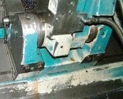
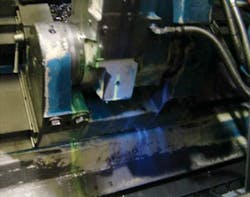
Once a system has been determined to have high consumption, schedule an inspection to identify the source(s) of the leakage, rather than initiate a repair. The consumption data pinpoints the problem system, while the inspection pinpoints the actual problem and action required. Quantify individual leaks for prioritization and cost evaluation. Ultraviolet dyes can highlight leaks for quick and easy identification. Schedule repair based on severity, difficulty to repair, and production availability.
Continue to maintain and update the documentation of this process. You may also want to track percentage capture, an indicator of lubricant volume tracked versus volume purchased. This will ensure that you stay on target and reach your cost savings objectives.
For more information, call (800) 662-4525, or visit www.mobil.com.
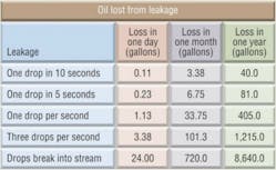
Oil lost through leakage
Common leakage points include: hose and tube fittings, pump shaft seals, cylinder rod seals, pinholes in tubing, and valve block O-rings.
From a safety perspective, when dealing with hydraulic lubricants it is important to realize that hydraulic oil leakage can occur as a high pressure stream capable of puncturing the skin. Oil injection under the skin can cause serious injury. Streams from pinhole leaks can be nearly invisible to the naked eye. Use caution when searching for leaks.
Dying to find the cause
Ultraviolet dyes are an effective tool for identifying individual leaks within a hydraulic system. They help to pinpoint active leaks in the presence of other oil and fluid films.
To properly use an ultraviolet dye test, follow these five steps:
- Add ultraviolet dye to the hydraulic reservoir as recommended by the dye supplier.
- Operate the machine normally to allow the dye to disperse throughout the system. It may be necessary to run several cycles at the end with metalworking coolants or other process fluids, which tend to wash the dyed oil away.
- Inspect the machine using a high-powered ultraviolet light for signs of the dye. Start in areas where leaked oil accumulates such as in drip trays, coolant systems, or basements. Once an accumulation is found, look for signs of oil flowing or dripping into the accumulation. The ultraviolet dye will illuminate oil along a path or stream. Trace this path back to its source.
- System consumption may be the result of one or many leaks. Quantify the rate of each find and compare the total against system consumption. Rates may vary with pressure, so observe the leak throughout the machine cycle if safely possible. Search until the number of leaks found accounts for the system consumption rate.


