Sealing involves not only preventing fluid from escaping the hydraulic system, but also keeping contaminants from entering the system. Exclusion plays a critical role in the successful function of hydraulic systems because contaminant ingression interrupts the sealing function, which can lead to system failure. The incorrect seal choice will undoubtedly decrease the life span and reliability of the entire system.
Many different products and techniques can keep contaminants out of a hydraulic system, and many offer improved sealing capability — but at costly tradeoffs. For example, redundant sealing systems or innovative material choices may provide improved exclusion ability, but can add friction to the system and may not perform well in all conditions. Complicated labyrinths can be effective, but often are difficult to machine and cumbersome install. Rather than looking for elaborate solutions, the answer may be as simple as customizing the exclusionary seal being used.
Requirements on sealing systems
Seals must fill a variety of requirements, any of which has the potential to drastically impede, or completely prevent, the proper function of the hydraulic system. The sealing system’s basic function of ensuring leak-free operation over a required lifetime is designed around the idea that a system works best if the sealing interface is kept clean. This plan does not include elements to prevent wear caused by contamination. Ingress of dirt, metal particles or even fibers, can interrupt the continuous sealing bead that occurs at a cylinder’s main rod seal.
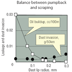
An exclusionary seal, often called the wiper, not only must prevent contaminant ingression into the cylinder, but also allow the minute oil film that remains on the rod to re-enter the system. Oil scraped off the rod by the wiper is often mistaken as system leakage because pooling from main seal leakage or from an over aggressive wiper both result in the same thing — a deposit of oil outside of the cylinder.
Aggressive exclusionary sealing systems can also affect the overall system friction, thus generating excessive heat. In addition to controlling leakage, sealing systems also affect system movement and forces, including smooth motion control and accurate positioning. Friction and stick-slip — caused by a jump between hydrodynamic lubrication (two surfaces separated by a thin film of oil) and boundary lubrication (two surfaces mostly in contact) — are key design considerations that must be minimized in achieving smooth and consistent overall performance. The performance of exclusionary seals can affect these functions. Therefore, they must also be considered during system design.
Problems and problem solving
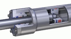
High-pressure cylinder sealing systems normally consist of four elements: the wiper, the rod seal (or main seal), the buffer seal (or secondary seal) and the wear (or guide) bands.
Wear bands — Although the function of the wear band is not intended to provide exclusion capability for the main seal, it often captures internal debris suspended in the oil. Metal shavings not properly removed during assembly or contaminants that get into the cylinder during fluid replenishment are often sources of short term leakage if they get to the main seal.
The problem of capturing contaminants in the wear band is that, depending on the position, the contaminants can scratch the rod in the area that contacts the main seal, creating a leak path. The best way to avoid this is to eliminate internal contamination before the system is put into service. This should include:
• ensuring that each component is clean (especially fluid) before it is installed,
• thoroughly flushing the entire hydraulic system, and
• providing an adequate filtration system.
Buffer seals — A buffer seal serves as a sacrificial barrier for the main seal. Although always beneficial, it is sometimes left out of systems to minimize the number of components, save cost in lower pressure and shorter life applications, or conserve space when it is at a premium. Although this seal is effective at lower pressures, its purpose is to prevent fluid at high pressure from reaching the main seal.
Like wear bands, a buffer seal typically is only exposed to internal contaminants, such as metal chips or other oil contaminants in the hydraulic fluid. These contaminants may become trapped in the interface between the buffer seal and piston rod. If this occurs, the wear element of the contaminant would be magnified because of the inherent function of the buffer — the pressure the buffer isolates from the main seal is directly transferred into the area where the contaminant is now trapped. As with the wear band, this can damage the rod surface, which will undoubtedly come in contact with the main seal area. Again, the best solution is to eliminate the potential for internal contamination, rather than count on the buffer seal to capture it.
Main (primary) seals — This seal is normally selected for its resistance to deformation, wear, and friction generation rather than exclusion. Most primary seals, also called rod seals, are usually made from special elastomers, polyurethane, or polytetrafluoroethylene (PTFE) and have the difficult task of keeping the oil in the system. In some cases, a beaded heel is machined or molded onto the non-pressurized side of the main seal to act as a contamination block, but that is not the main purpose of the heel. A limitation to the heel is that it may be exposed to high pressure if a buffer seal is not used.
When properly designed, the main seal rides on a minute film of oil that is held between the seal and shaft. When the piston extends, the oil film leaves the cylinder and must re-enter during stroke retraction. Many seals are designed to have a clearance between the heel and rod to allow for this “pump-back” of the oil film back into the cylinder. This reveals a second drawback to a beaded heel: it impedes pump-back of fluid.
The beaded heel can actually scrape off enough oil that pressure builds between the main seal and wiper seal cavity, thus requiring special venting type exclusionary seals. However, a beaded heel is effective in reducing overall system friction at low- to mid-level pressures.
Because the heel is acting as a wiper, if some form of contaminant becomes trapped in it, the same principle described with the buffer seal comes into play. Although an abrasive effect can take place at the bead-rod interface, with no pressure, the bead simply holds the contaminants in place.
System pressure affects the main seal if no buffer seal is used. Although many seal materials resist deformation, at the higher pressures the seal normally deforms to the point of complete collapse onto the shaft. At this point, the abrasive effects of the contamination become amplified, likely resulting in rod damage.
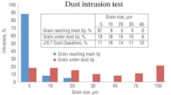
Wipers — The wiper is the most effective means of keeping contamination out of the system. A wiper often is not considered a customizable feature because so many variations are available. Plus, its function may be overlooked by designers.
Wipers come in several different styles in a variety of materials, but the three key design elements are: the design of its wiper lip; the load used to create the wiping effect; and the material used to resist wear caused by aggressive media.
Wipers are often made of:
• rubber for low contamination at moderate speeds,
• urethane for high contamination at moderate speeds,
• PTFE for light contamination at high speeds, or
• metals (brass or bronze) for extremely heavy contamination at low speeds.
No matter what the material, the theory behind the wiper is to create a wiping action that can vary depending upon the design. As a practical example, think of trying to scrape water off your kitchen counter using first a notebook, then a rounded or sharp edged cutting board and finally a metal spatula. Each would have a uniquely different effect. Wiper designs also provide unique characteristics.
The load is affected by the material used and the design of the seal, but the subtleties of the design at the point of contact between the wiper and rod are very critical to the application. If a stiff component applies a heavy load to a small area with a sharp contact point, a very good scraping action will be created. However, this interface may not be ideal for allowing fluid film back into the system. On the other hand, if a flexible component applies a light load to a wide area with a round contact point, this scenario will allow the oil film back into the cylinder, but it will not be nearly as effective at keeping contaminants out.
Most applications reach a compromise between two situations. A wiper is designed to remove as much contamination from the rod as possible while still maintaining a thin film of fluid on the rod.
Joel Johnson is Global VP of Technology at Simrit. For more information, call (866) 274-6748 or visit www.simritna.com.


