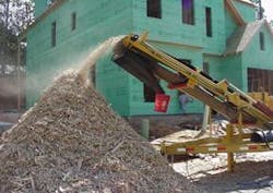
To most of us, recycling means lugging a bin of cans, bottles, plastics, paper, or cardboard — or any combination of these — to the curb for pickup by our community's recycling personnel or to a recycling center. Residential materials, however, are just the tip of the recycling iceberg. Industry generates huge amounts of byproducts that once were discarded but now are recycled — in essence, turning trash into cash. In the construction industry, for example, clearing land to make way for a building can produce a mountain of surplus soil that can be transported to an area where it is needed. Brush and branches can be run through a chipper-shredder to produce mulch for subsequent landscaping, but tree stumps call for a different process. Here, stump grinders have emerged as a specialized tool to quickly transform tree stumps into shredded mulch for landscaping. As you might expect, stump grinders rely heavily on hydraulics for the high torque and power needed to reduce wood in its hardest and toughest form to a pile of splinters.
For people involved directly in the industry, recycling is becoming more competitive and more high-tech. Many high-production machines are being developed to process industrial and municipal waste into a useable commodity. Some machines, like stump grinders, excel in performing one specialized function more effectively than anything else. Others are developed to perform numerous sequential operations automatically to reduce or eliminate the labor and human intervention otherwise required in processing. To demonstrate the innovative uses of hydraulics in the recycling industry, we will describe several such machines. Chances are, your job does not involve designing machines for recycling, but you may be able to apply some of the principles described here into the machines you do design.
Torque tackles tough tires
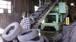
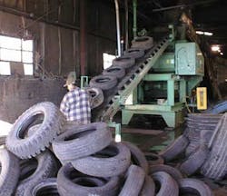
For most recycling processes, tires are shred into chips, but what makes this so difficult is having to cut through soft, impact-resistant rubber that contains hard, strong, steel reinforcement. High-speed shredding is not the answer, because high speed would generate heat. This would soften the rubber and make it almost impossible to cut the tires. However, low-speed shredding requires tremendous torque.
To transmit low-speed, high-torque power for shredding, machines could use a gear box to reduce speed from an electric motor and multiply torque. This often proves impractical, because the gear box would be heavy and bulky, which would increase structural requirements. Also, shock loading often occurs when shredding blades suddenly strike steel reinforcement. Moreover, tires get jammed between shredding blades, which makes it necessary to quickly reverse direction of the blades to free the jam. Having to quickly and frequently reverse rotation would prove especially challenging for an electromechanical drive because of its high inertia.
Hydraulic technology rises to the occasion by offering drive components that are much less bulky and more well suited to the demands of high-torque shredding. For example, one company's twin-roll tire shredders are driven directly by a pair of radial-piston motors through a hydraulic system provided by Hagglunds Drives Inc., a division of Bosch Rexroth.
Each motor has a displacement of 1084 in.3/rev and can generate up to 66,840 lb-ft of torque. The motors are rated 14,390 lb-ft/1000 psi, and can handle 5000 psi, so their maximum torque rating is actually 71,390 lb-ft. Severe jam ups that could damage gear drives simply cause these motors to stall. Stall conditions increase pressure in the hydraulic system, which triggers valves to automatically reverse rotation of the drive to free the jam up.
One particular challenge of the application was mounting. The radial-piston motor produces high torque in an envelope that consumes relatively little axial space. Butthe short center distance between shredder blades and the large diameter of the radial-piston motors prevents mounting them side by side in this application. The short center distance also prevented using flange-mounted motors, and foot mounting would have required an extensive framework. Instead, each motor is mounted directly to a shaft at opposite sides of the shredding chamber and is kept from rotating by a torque arm. This arrangement provides a compact, simple, and easy-to-install drive system.
Hydraulics drives clarifiers
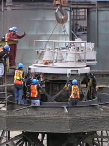
The heart of the clarifier is the drive. Conventional clarifier drives consist of an electric motor turning the rotating rake through a belt or chain drive and gearing to reduce speed and increase torque. Drives built by DBS Mfg. Inc., Forest Park, Ga., however, use gearing in combination with hydraulics to transmit power. Andrew Bain, director of engineering at DBS, explained that hydraulic drives are more reliable, last longer, and require less maintenance than chain or belt drives. "Especially when greater loads and precise torque control is required, hydraulics is the best engineering solution. Our drive units are designed to operate 24 hours a day for maany years, and it's not uncommon for them to last 30 years or more."
As with many hydraulic systems, DBS drives have the pump mounted submerged in the reservoir. However, Bain said DBS takes this concept a step further by submerging essentially all of the hydraulic components in the reservoir: valves, tubing, fittings — even the low-speed, high-torque motor. "Submerging everything in the reservoir eliminates leakage problems almost completely," reveals Bain. "If the fitting connecting the pump outlet line to the valve inlet port leaks, the fluid leaks harmlessly within the reservoir."
Bain continued that speed and torque control are important for clarifier drives. "The rake typically rotates at only 0.06 rpm. If you go faster, you'll stir up the sludge blanket and prevent particles from separating out of the water. If the rake moves too slowly, too much sludge collects, causing too thick or too dense a sludge blanket. Too thick or dense a sludge blanket increases the torque required to direct material into the drain, which could cause a malfunction. With hydraulics, speed is proportional to flow, and torque is proportional to pressure, so you can easily control torque and speed by regulating pressure and flow." Incorporating a switch to monitor system pressure allows appropriate action to be taken automatically — such as sounding an alarm or shutting down the drive if pressure reaches the cutoff threshold.
When precise speed control is also important, pump displacement provides a means of regulating flow, and, therefore, speed. This generally is accomplished with a variable-displacement pump. Another design variation is to use a fixed-displacement pump and provide a hydraulically actuated jack to raise the rakes if the sludge blanket becomes too thick. This would cause the rake to plow only the upper portion of the sludge blanket toward the drain. In this arrangement, rotational speed of the rake would remain constant, but elevation would be controlled by pressure. For other applications, speed, torque, and elevation all can be controlled to optimize process requirements.
Crushing a negative icon
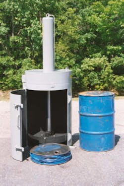
The Model 7000 drum crusher uses a 6-in. bore hydraulic cylinder to reduce drums to as little as one-eighth their original size, which makes it much more economical and practical to recycle steel drums as scrap. The standard in-plant drum crusher uses a 5-, 7.5-, or 10-hp electric motor to drive a pump that delivers 12, 15, or 20 gpm, respectively. The difference between each size is cycle time; the 5-hp size requires 70 sec to crush a drum, and the 7.5- and 10-hp sizes require 55 and 38 sec, respectively. With a relief valve setting of 3000 psi, all sizes produce a crushing force of up to 85,000 lb. An optional model with a 7-in. bore cylinder delivers up to 115,000 lb at 3000 psi.
MacMillan Hydraulic Engineering Corp., Skokie, Ill., builds the hydraulic power units (HPUs) and supplies many of the hydraulic components to Drumbeaters. Robert MacMillin, president of MacMillin Hydraulic Engineering, says that users want a machine that crushes drums quickly, is reliable, and will last a long time. Also, they are not willing to spend a lot of money for a machine that basically processes scrap. Therefore, he says he chose to use a high-low pump that operates at high volume and low pressure when no or little load is encountered. Once fluid pressure increases due to resistance from the load, the pump shifts to a low-volume, high-pressure mode.
The simplicity of the hydraulic system using manually actuated valves provides years of reliable operation. To add longevity, the hydraulic cylinder is designed to extend to only within 3 in. of the bottom of the crushing chamber. MacMillin explained that preventing the cylinder from bottoming out extends its life by eliminating end-of-stroke impact that otherwise would result.
The Model 7000 crusher easily can be moved from one location to another by a fork lift. If necessary, the HPU can be separated from the crushing chamber via quick-acting couplings or mounted remote from the crushing chamber when space is tight. For users that prefer to bring the crusher to the drums, Drumbeaters offers a trailer-mounted transportable unit. With this configuration, the hydraulic pump is driven by a gasoline or diesel engine.
Drumbeaters points out that their crushers are used for more than compressing drums. An optional triple-rinse system accessory removes fluid from drums and rinses the drum in accordance with federal regulation #40 CFR, Part 261.7. Their crushers can also be used to squeeze fluids out of filter media or for compressing waste materials into bales.
Rotating-case motor powers grinder
To maximize reliability, engineers at Packer Industries wanted the cutter drive of their wood waste grinder to be driven directly by a high-torque motor, and without mechanical couplings or auxiliary bearings. All of these requirements were met by specifying a model SMA radial-piston motor from Rotary Power Inc., Columbus, Ohio.
The inherent design of radial-piston motors produces low-speed, high-torque power — in this case, 300 hp from a motor with a displacement of 122 in.3/revolution, rated for 5000 psi maximum continuous pressure and maximum speed of 380 rpm. Because the SMA motors are designed to accommodate high external loading, they are mounted inside cutter drums and need no external bearing supports. Pressurized fluid is routed to and from the motor through its stationary shaft. Rotating unions inside the motor route fluid from the stationary shaft to the working chambers.
Another advantage of Packer's wood waste grinder is an ergonomically designed cab. Hydraulic functions and components are controlled electronically, so the operator is not subjected to the noise and heat associated with pilot-or direct-operated valves. Pump displacement is controlled electronically from inside the cab — a feature that not only provides operator comfort and convenience, but adds to productivity.
Clean fluid helps convert garbage into energy
The garbage is burned in four large incinerators that are fed by hoppers that use hydraulics to dump their load through a fire door that is opened and closed by a 53-in. stroke hydraulic ram. Heat generated by the incinerators turns water into steam, which powers turbines that generate electricity. The floor of the incinerator has three sectioned transfer blocks that stroke back and forth 56 in. to push garbage progressively farther into the incinerator. When it reaches the opposite end of the incinerator, the garbage has become ash and is pushed out of the furnace by a 108-in. stroke ram.
Specifying the right drive system to operate 24 hours/day in this extremely dirty environment moving heavy loads while subjected to very high temperatures proved instrumental to the project's success. The facility's Design Build Group chose hydraulics as the driving force for most of the required motions after evaluating cost, reliability, and efficiency. Seven years of successful operation have confirmed the wisdom of the choice.
Four hydraulic systems, each dedicated to one of four incinerators, contain a 30-hp hydraulic power unit (HPU) that produces 15 gpm of flow at pressures to 2000 psi to drive two pairs of double-acting cylinders- one pair for the fire door and one for the loader ram. Single double-acting cylinders actuate the hopper door, ash-removal ram, and three transfer rams. All four incinerator have a second HPU — rated 5 hp to deliver 6.6 gpm at pressures to 1100 psi — to power a hydraulic motor that drives an ash removal conveyor. Every HPU is also backed up by an auxiliary unit with identical performance specifications.
Inherent advantages of hydraulics address the two most hostile operating conditions of this application - high temperatures and extremely high concentrations of contaminants. To deal with high temperatures, designers specified Quintolubric 822-220 (which has since been replaced by Quintolubric 888-46) fire-resistant hydraulic fluid from Quaker Chemical Corp., Conshohocken, Pa. This fluid has a viscosity of 220 SUS at 100° F, which conforms to ISO 46, and is approved by Factory Mutual Research Corp. for fire-resistant performance.
To deal with the potentially high levels of contamination, programs were established to continuously filter the hydraulic fluid and monitor its cleanliness. Initial fluid contamination was consistent with an ISO rating of 19/16. This is equivalent to 4.5 million particles larger than 5 µm per gal of fluid. Much of this contamination is ash, which not only can harm components, but is caustic and can degrade chemical properties of the fluid as well. Therefore, engineers sought to improve fluid cleanliness to a level consistent with an ISO rating of 15/13.
To achieve this goal, engineers incorporated a number of improvements to the filtration systems of all hydraulic systems. The hydraulic systems were installed using only 140-µm suction strainers for filtration. Bob Barber, maintenance manager at Peel Resource, said that within the first year of operation, return line filters were installed to improve cleanliness. This consisted of 25- and 12-µm elements piped in series in the main return line. Each reservoir was equipped with cleanout ports and desiccant/filter breathers to help exclude the ingression of airborne contaminants and moisture.
More recently, Barber explained that off-line filtration was provided for each reservoir to reduce contamination even further. Supplied by Triple R America, Toronto, each of these kidney loop filtration units contains three filter elements, each rated for 1 gpm. Piping them in parallel yields a total flow capacity of 3 gpm.
According to David Murray, president, Triple R America, using three optimally sized elements provides more efficient filtration than a single, larger element. Consequently, the three elements piped in parallel maintain a beta rating of 217 for 1-µm particles. Murray explained that actual certification testing was conducted for 2-m particles, which yielded a beta rating of 434.
Ultimately, this combination of improvements allows PRR to maintain hydraulic system cleanliness at an ISO 12/9 rating, essentially reducing the number of particles greater than 5 µm by a 99.3%.
