This file type includes high resolution graphics and schematics when applicable.
Unrestrained hydraulic tubing can emit sound as though it were a tuning fork. Fluid velocity, pressure, and line size all contribute to the high-frequency vibration, line shock, pressure surge, and sound, which are prevalent in many hydraulic machine operations. Shock, pressure surge, and vibration will flex metal tubing. This flexing can cold-work the tubing, particularly around connectors. The consequences are split fluid lines.
Accordingly, the fastening components used have progressed from simple clamps to specially engineered pipe and tubing supports. A properly designed and installed piping-support system can reduce noise pollution, risk to property and personnel, and environmental damage caused by the discharge of hydraulic fluid from a damaged line.
Effects of Vibration
Pipe supports should control vibration and absorb shock. Pumps and valves are the greatest cause of vibration and shock, owing to the drastic pressure and fluid velocity changes that occur in these components during operation. While intensive research has reduced pump- and valve-induced vibration, it is still considered a problem for the entire piping and tubing system. Through piping and tubing, vibration, shock, and related noise are transmitted and amplified. Note that pumps are the greatest source of noise, and reservoirs provide the strongest amplification.
Excessive noise for plant personnel is only one negative effect. More importantly, if pipes and hoses are not properly supported, vibration may cause fittings and flanges to loosen. This can lead to increased safety risks for plant personnel, downtime, higher maintenance costs, inefficiency of the system (due to air causing cavitation in pumps and valves), and loss of hydraulic fluid. It is no overstatement to say that the cost, danger, and other consequences of hydraulic leaks as a result of loose fittings and flanges can be alarming.
Resilient Supports
Resilient supports have been developed to dampen the vibration in piping systems. Several types of supports are available that absorb shock and vibration to different degrees. These products use various materials—including wood, rubber, metal, and thermoplastics—and designs to accomplish this task. The support systems generally fall into two categories: individual supports that hold single tubes, and multi clamps to secure two or more lines. Most systems can accommodate pipe and tube sizes from 3/16 to 24 in., while others handle sizes up to 42 in. Many will stack for several tiers, and they can be fastened down with a weld base or to a mounting rail.
Support Material
Although wooden blocks and rubber grommets are adequate for supporting pipes and tubing, they have several disadvantages. Wood tends to dry out, crack, and lose its absorption properties. Wood is also a relatively expensive support material. Aside from its lack of chemical and abrasive resistance properties, rubber is generally only used in conjunction with some kind of steel strap or surround, adding to the cost and complexity of these supports.
Multi-tube Support Systems
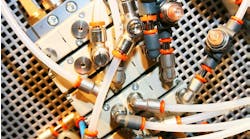
Generally, multi-tube clamping systems are manufactured from pressed steel. The tube or pipe is held by a split rubber or plastic grommet located in the steel clamp body; this grommet is held in a steel body by a retaining ring molded into it. This type of clamp is ideal for general hydraulic and pneumatic systems that do not generate excessive high-frequency vibration; it is satisfactory for line diameters up to 2 in. and temperatures to 250° F. Several models offer the added versatility of interchangeable grommets to hold different size tubing while using the same clamp assembly.
Some multi-tube systems allow fitting inserts or junction adapters to be placed between the clamping halves. These inserts permit the clamp to serve as a bulkhead connector plate or junction block, tube-to-tube connection, tube-to-hose connection, or terminal. Another feature of some multi-tube systems is fixed centerline distances, both horizontally and vertically. This can be either an advantage or disadvantage, depending on the installation.
Individual Tube Clamps
Some systems clamp individual tubes, which allows for the design of a modular clamping system to accommodate as many tubes as necessary. Most clamping systems are for clamping individual lines. Single clamps are either fastened directly to a mounting surface at predetermined positions or located in a mounting rail, allowing for adjustment after mounting.
Individual supports can be either molded plastic with an identical upper and lower half, or of the rubber grommet design with a molded grommet surrounding the pipe or tube. Steel retaining pieces hold the grommet tightly around the pipe and fasten to the mounting plate.
The grommet design allows for quick and easy installation and adjustment, but is not suitable for large diameters or where heavy shock and vibration are present. This style of support cannot be stacked easily.
Thermoplastic Supports
Manufactured by injection-molding processes, thermoplastic supports consist of identical upper and lower halves that are held together by one or more steel bolts, often in conjunction with steel bases and cover plates. Using identical upper and lower support halves eliminates potential confusion during installation in the field.
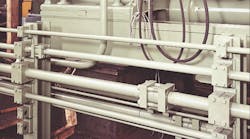
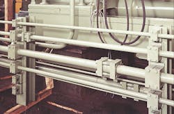
To attach the support, base plates are either tack-welded or, in the case of high-vibration applications, continuously welded to any available structure. To further simplify installation, multi-position rails have been developed to accommodate several individual supports side by side without wasting space. Additional advantages result from breaking down traditional multi-tube clamps into individual supports. They are less expensive and easier to install, and maintenance or moving of pipes and fittings is greatly facilitated by providing access to one particular line without disturbing adjacent lines. Some multi-tube clamps solve this problem by cutting the upper half of the unit for convenient removal of several tubes for service.
Individual supports are also ideally suited to compact and secure pipes and tubing in cramped areas. Several of the supports can be stacked on top of each other, resulting in an uncluttered yet efficient use of available space.
Routing
After analyzing your hydraulic system, route your tubing by the most direct route. One manufacturer suggests routing lines along the bases of the machines. Beware of obstructions, moving parts, contours, and service openings. Plan around them: If the base routing is not economical, consider upright carriers for partial line suspension. If this is not practical, full overhead suspension is the last resort.
One particular feature that saves trying to “measure in the air” is a clamp with standard centerline dimensions regardless of tubing size. This is helpful when laying out original tube runs.
How Far Apart?
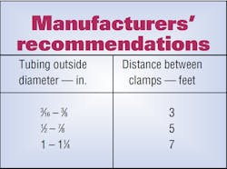
Manufacturers recommend spacing between clamps as shown in the table. All tubes should be clamped on both sides of a bend, as close to the bend radius as possible. This prevents tube movement if internal hydraulic shock occurs. This spacing permits a tubing system wall-thickness reduction from 0.095 in. to 0.065 in. with no splitting in the reduced thickness tubing walls.
A well-designed fluid power system will include a tube and pipe support system. The fluid system may be for a single machine, a central system that serves an entire plant, or any size in between. Proper tube support pays dividends—for the designer, maintenance crew, and plant personnel alike.
How to Mount Clamps
Methods of fastening clamps to supporting members vary. Some multi-clamp assemblies can be bolted on, others can use a tapped hole, and still others can be secured to a suspended column by bolting through special mounting adapters that use holes in the clamp assembly. Power-driven studs are available for wood and masonry, too.
Other multi-clamp sections, and some individual clamping models, have feet or brackets, which are welded to the supporting surface. The lower half of some are simply welded in place. Some individual clamp types can be anchored in channel-type metal pieces, which are welded or bolted to the support surface, and again allow designing the overall clamp assembly as wide as desired. Most support systems can be mounted on strut-type rails that already may be present in some installations, allowing light-duty hydraulic and pneumatic lines to run alongside water and gas lines.
When stacking clamp assemblies, the usual holding method is with studs that thread into the bolts or studs of the lower clamp assembly. One variation provides a wider bottom clamp assembly; the bolts of the upper assembly thread directly into the top of the lower clamps. When stacking supports horizontally, take care that the weight of the assembly does not exceed the manufacturer’s recommendations.
This file type includes high resolution graphics and schematics when applicable.


