After years of anticipation, “Spider-Man: Turn Off The Dark” opened at the Foxwoods Theater on 42nd Street in New York City only weeks ago. Many motion control disciplines had to come together to create this Broadway spectacle, and PRG Scenic Technologies, New York, was the primary contractor for the automation and hydraulic systems, while Fisher Technical Services designed and manufactured flight systems for Spider-Man.
The first challenge was dealing with the infrastructure of the theater. The electrical service allocated to hydraulics only allowed for 200 hp to be pulled from the power grid, even though 700 hp is required during peak periods of motion.
Hydraulic power unit and circuitry
After careful study of the stage effects sequences, engineers determined that adequate time between stage moves was available to charge a large accumulator bank to supply oil during peak flow periods. The bank of 12-in. bore piston accumulators has a total capacity of 138 gal, supplemented by 205-gal of pressurized nitrogen in adjacent 12-in. bore receivers. Combined with pump flow, the accumulators supply peak flow of 600 gpm at 2000 psi.
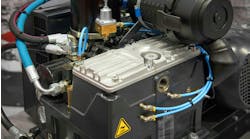
Two 50-hp electric motors each drive a 100-cc model PD variable-displacement axial-piston pump from Parker Hannifin. Each pump-motor combination delivers up to 22 gpm of fluid at working pressures to 3000 psi. Proportional relief valves on compensator control lines of each pump ensure that system pressure can be adjusted by command signal from a closed-loop electronic controller. This feature showed its purpose when commissioning and testing the entire system at reduced pressure.
The system’s reservoir holds up to 300 gal of fluid and has return line filtration capable of returning full flow of the accumulator rack during extreme stage moves. A main system return header was constructed with six 2-in. Code 61 flanges feeding two Parker RF7 tank-top filters. In addition to return line filtration, a custom manifold combines each pump outlet and routes all HPU flow through a high pressure Parker 50 P filter. Additional fluid conditioning is provided by a 16-gpm filtration and cooling loop.
Driving multiple loads
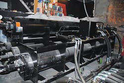
The hydraulic system drives several different types of stage platforms. Farthest downstage are three scissor lift devices that, from the basement, will drop a 10-ft by 30-ft area of the stage down 10 ft and completely out of site. Although this stage is in three sections, which sometimes operate separately, Parker D91FH hydraulic servovalves and finely tuned software allow it to appear to travel as a single platform when called for. One of the lifts can propel the Spider- Man character vertically at an impressive 4 ft/sec.
Each lift has two cylinders mechanically linked to each other within a tight space. The close quarters prevented equipping the cylinders with mechanical rod locks, which are used to hold a cylinder∏s piston rod in place if a hydraulic line ruptures. Instead, a custom-designed counterbalance valve manifold serves each pair of cylinders. The counterbalance manifold ensures that the lift will hold position if a hydraulic line breaks.
Cylinder motion is controlled through a valve manifold mounted nearby that provides two functions: choreographed moves and emergency positioning. During normal show operation, a size D08 D91FH servo-style proportional valve from Parker Hannifin controls the lift. However, when necessary, a single D03 lever valve located on the lift control manifold over-rides the main D08 valve to fully lift the platform and also raise a fire curtain to seal off the back stage area from the house.
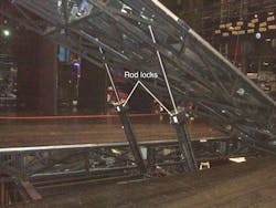
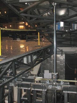
A second type of stage platform consists of three 30-ft long ramps that extend downstage to upstage. The ramps lift in a raking effect ∇ meaning that as the back of the ramp lifts up, it also moves toward the audience. Six 3.25-in. bore tie-rod cylinders with 2.5-in. rods and 114-in. strokes operate the ramps. Analysis on rod column strength was a critical factor in design due to the lengths of the rods and the heavy loads on the ramps.
All ramps can operate together and appear as one stage lifting 14 ft upstage. Again, hydraulic servovalves and controls designed into the system by PRG Scenic Technologies bring the stage to life and make the highspeed movement of four individual stages seem like one. The cylinders are Parker Type 2H, which come with SAE O-ring ports as standard to provide leak-free operation. Each also contains an integral magnetostrictive linear position transducer from Balluff to provide continuous feedback of cylinder position. Finally, a rod lock fitted to the front flange of each cylinder holds its piston rod in place once a platform reaches its set position. The controls
Of course, when more than 2000 people per show see your work, takeoff and landing of moves must be smooth and realistic. Tuning is of utmost importance — and especially challenging — when large masses accelerate and decelerate rapidly. Without it, jerky motion will occur. When setting a platform 14-ft above stage level with dangling artists, safety protocol states that cylinders should be locked in place with no chance of movement in any way. This happens with a rod lock at the rod end of the cylinder. The clamp simply locks the rod in place, preventing any piston drift.
To help achieve smooth motion, Atlantic software engineers worked with PRG Scenic Technologies to develop “swell up” code to prevent cylinder jerk during moves when the rod lock is active. This code records induced hydraulic pressure on the cylinder from the stage at resting position. The pressure then swells up hydraulically in a subroutine prior to movement. This causes the platform to hold firm when the lock releases to prevent any sudden motion, or bump.
The art of tuning takes on a whole new definition when it comes to hydraulics and scissor lifts. The pressure requirements from full retraction to full extension vary significantly, enough where PID settings at one elevation would cause drastic instability at another. Again, subroutines are set so PID setting will be adjusted automatically by position feedback from the linear transducers.
For more information, e-mail [email protected], or visit www.aitzone.com. Visit Scenic Technologies, A Div. of Production Resource Group for more details on their technology.


