Thousands of press operators today are trying to reduce their production costs and stay competitive with higher speeds, smaller batches, and greater machine uptime. The cost for a catastrophic press failure is at least thousands of dollars in lost production time and die replacement costs. On the high end is the loss of a key operator from injury or a customer that takes his business elsewhere rather than run the risk of falling behind schedule again.
Of course, today’s most modern hydraulic and pneumatic presses have a variety of OSHA mandated protection systems in place to ensure operator safety. Guards, interlocks, electro-sensitive and optoelectronic devices, emergency stop circuits, and other redundant systems have helped make presses safer than ever. But when it comes to safeguarding the presses themselves or dies from expensive damage, standards in the U.S. fall well short of their European CEN counterpart, which states in prEN 693 Machine tools Safety Hydraulic Presses: “Where there is a risk. . . from a gravity fall of the slide/ram, a mechanical restraint device, e.g. a scotch, shall be provided to be inserted in the press. . . On presses with an opening stroke length of more than 500 mm and a depth of table of more than 800 mm, the device shall be permanently fixed and integrated with the press.” A similar CSA Standard (Z142-02) exists in Canada.
Faulty or fail safe?
For most American press operators, however, a ratchet bar, locking bolt, or latch is all that’s standing between them and a catastrophic crash if fluid pressure is suddenly lost or the lifting mechanism breaks. When functioning properly, the ratchet system — usually running the length of the press stroke — does an adequate job of arresting the fall of the ram and preventing a catastrophic crash. A spring latch will automatically extend to engage the teeth of the ratchet at some point before a crash can occur.
However, the ratchet is a mechanical part that wears after repeated press cycles and can begin to show signs of wear that are difficult to detect visually and probably can’t be heard, even by the most experienced operator. Even though the latch doesn’t engage the ratchet teeth on its return (up) stroke, it still slides over them. So over time, the teeth, spring, and latch still wear every time the ram is raised for the next part. The ratchet and the end of the spring latch can wear to the point where a fall can’t be prevented.
In addition, locking bolts and latches often operate only at the top of the stroke, and ratchet bars operate at fixed intervals. Consequently, the ram must often be retracted to its full stroke after every cycle, even if the work piece requires only a short opening stroke. This can add considerable — and expensive — time to every cycle.
Safety catcher to the rescue
In Europe and Canada and elsewhere in the world, most presses are equipped with a safety catcher from Sitema GmbH & Co., Karlsruhe, Germany (available in North America from Advanced Machine & Engineering Co., Rockford, Ill.). The safety catchers satisfy the requirements of CEN and CSA safety standards, protect presses from catastrophic crashes, and allow operators to optimize the stroke for any size part.
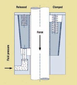
The safety catcher uses a wedging action to prevent a press from falling from any position if a hydraulic or pneumatic system pressure fails, or if a rope, chain, belt or toothed drive breaks. The wedges are spring applied and released by fluid pressure. The device is also self-intensifying, so as downward force increases, so does clamping force.
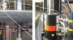
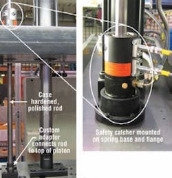
A typical installation is shown in the accompanying photos. A cylinder’s piston rod is mounted to the top of the press’s platen and extends through the press crown and the safety catcher housing. The safety catcher housing is securely fixed to the machine crown frame and surrounds the piston rod, which is free to move during normal operation. Fluid pressure holds the wedge shaped clamping jaws inside the safety catcher’s housing away from the rod so it can move freely.
The safety catcher instantly engages when fluid pressure is lost or released. When this occurs, a spring causes the clamping jaws to firmly contact the rod.
Any downward movement of the rod initiates the self-intensification feature securing the load. So the energy of the descending load applies additional clamping force. If the load continues to increase, the safety catcher continues to hold the rod in a fixed position until a pre-determined static holding force limit is exceeded — about three to four times the retaining force. When this occurs, the safety catcher provides a braking action to dissipate the kinetic energy of the descending load.
Only when fluid pressure is restored in conjunction with the equivalent reverse movement of the rod are the clamping wedges released, making the Sitema safety catcher inherently fail safe.
This information was provided by Ken Davis, of Advanced Machine & Engineering Co. For more information, email [email protected], or visit www.ame.com.


