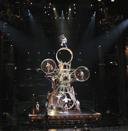
When the minds at Cirque du Soleil and McLaren Engineering Group, West Nyack, N. Y., asked Atlantic Industrial Technologies (AIT) to create something that had never been seen in the entertainment or theatrical world, the challenge was set. Cirque wanted to take industrial applications and modify them to suit the needs of their newest, and most ambitious, production. Stretching the boundaries of human physical capabilities is nothing new to Cirque du Soleil, but pushing the laws of physics is altogether different. After many hours of weighing theatric effect with feasibility, the final design emerged.
It was the task of AIT, Shirley, N. Y., to design a hydraulic system that would lift a structure weighing more than a Boeing 757 at a speed of 2 ft/sec. It would have to decelerate in 1.5 sec, position to 0.10-in. repeatability, and withstand the changing center of gravity caused by the stage tilting and rotating. The first priority in all aspects of the project was the safety of the artists.
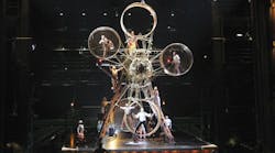
The MGM Grand Hotel & Casino in Las Vegas is the home of Cirque du Soleil's new epic, KÂ, a saga of separated twins who embark on a perilous journey to fulfill their linked destinies. Danger lies in wait for them at every turn. Archers and spearmen hunt the twins relentlessly, as their quest takes them through a succession of challenging landscapes, from a mysterious seashore to mountains and forests.
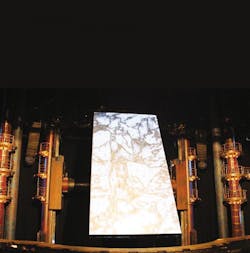
The stage, called the Sand Cliff Deck, accompanies the twins all throughout the 90-minute tale. It begins as an ancient ship emerging from the depths of the theatre, transforms into a vertical battleground, and then an ice glacier as projected images bring the stage to life. The Sand Cliff Deck is the largest of several moving performance spaces in the show. It weighs approximately 80,000 lb; combined, the support structure and Sand Cliff Deck weigh 350,000 lb.
Lifting the stage
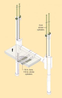
The 50 by 25 ft rectangular stage is mounted to a gantry that is lifted by four hydraulic cylinders along two columns that are 60 ft apart. The 12-in. bore, 70-ft stroke cylinders were manufactured by Parker Hannifin's Custom Cylinder Div., Eugene, Oreg. The original design called for longer stroke cylinders, but an industrial furnace large enough to harden the rods doesn't exist. Even at 70 ft, the 5-in. diameter rods had to be inserted diagonally to fit into the furnaces. Another challenge was transportation of the cylinders. There are very few tractor-trailer rigs that can transport a 75-ft cylinder. Special trusses were designed for cylinder protection during voyage from Eugene to Las Vegas. These cylinders, when totally extended, are almost as high as the Statue of Liberty and are the largest ever manufactured by Parker Hannifin.
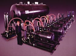
The four vertically mounted cylinders require flow of almost 2200 gpm for the 2-ft/sec lift. This is accomplished by 10 Parker PE series piston pumps sized at 145 cc/rev and driven by five 250-hp motors. Each of the five pump sets produces 130 gpm. Significant dwell time occurs between stage moves, which allows charging accumulators with pressurized fluid. The balance of the flow required is supplied by a farm of 34 50-gal Parker accumulators and 17 350-gal pressurized nitrogen tanks (bottles).
The cylinders are mounted rod down above the stage gantry, and perform the lifting function while retracting. If the cylinders were mounted rod up, they would have to push the stage up. This would cause buckling of the 5-in. diameter, 70-ft. long rods. By mounting cylinders rod down, the rod is always in tension, eliminating the likelihood of buckling. Servo control manifolds are mounted to the rod ports of the cylinders. Each of the four cylinders is controlled independently by its own servovalve manifold. This valve concept utilizes a 3-way, 80mm proportional valves from Atos, York, Pa., and a Parker D3FH series zero-lap servo solenoid valve. The two valves work together to provide both the high flow and fine resolution required.
Oil is fed to the rod side of the cylinder only, the stage is lowered by metering out the oil in a closed-loop circuit from all four cylinders. The reason for not pressurizing the cap end of the cylinders is the fear of bending a cylinder rod, should an anomaly occur in the servo system. It could take only 500 psi on the cap end to bend and damage a 5-in. rod extended 70 ft, if the right conditions exist.
The hydraulic oil chosen for the project was Cosmolubric B220 — from Houghton International Inc., Valley Forge, Pa. — for its fire resistant properties. Between the reservoir (4000 gal) and the piping, provide by GS Hydro, Houston, more than 7000 gal of hydraulic fluid is contained in the theatre and annex building (which houses the hydraulic power unit).
The hydraulic system was designed to run at 3900 psi and produce 6000 hp during peak flow and pressure conditions for 40 sec. After testing, the operating pressures were lowered to 1700 psi.
Tilt and spin
The stage must also tilt from 0° (horizontal) to 100°, where the stage appears to be a great wall in front of the audience. As the stage is tilting, it can also spin infinitely at up to 4 rpm. The speed an artist may see while spinning at the end of the stage is 25 ft/sec. The spin axis is accomplished utilizing a 100-hp vector motor on a 800:1 gearhead. A vector motor is a closed-loop, high-hp electric motor that can run at very slow speeds.
The stage platform that lifts, tilts, and spins is 6-ft thick and contains over 100 axes of its own automation. Inside the stage, the controls all around make a person feel more like an astronaut than a stage technician. During the tilt and spin of the stage, the on-board technicians must hold on tight, as they can be spun at 10 rpm.
The stage is tilted with four Parker 10-in. bore, 110-in. stroke cylinders. The control manifold contains two D81FH Parker zerooverlap proportional valves, which pass about 80 gpm each during a full-speed tilt. The stage will tilt 100° in less than 40 sec. During one scene, the tilt will dump a beach set, sand and all, into the depths of the theatre. In another scene, the tilted stage becomes a battlefield of acrobats while images are projected onto it.
Net winch
Artist safety is of utmost importance to the MGM Grand Hotel and Cirque Du Soleil. Two retractable 50-ft diameter safety nets sit below the stage as it lifts, tilts, and spins. Due to space and noise constraints, 14 hydraulically driven winches were chosen to set and strike the nets. Hydraulic winches use two-speed (dual displacement) motors for a wide speed range and are controlled by a proportional directional valve for fine speed control. A solenoid valve on the motors will shift the motor's piston swashplate from hi-torque/low speed to low-torque/high speed. Eight of the winches use a mooring control circuit, which allows the net to move as a whole while under constant tension. An on-board encoder and pressure transducers provide feedback to the controls — the net position as well as the net's tension. Perfect tension on the net must be maintained for optimal artist safety. The nets are set and struck over a dozen times during each performance.
Controls
Any time you lift 150 tons at 2 ft/sec to within 0.10-in., controls must be extremely fast and reliable. A Delta Tau fiber optic servo control loop was employed for this task. The stage lift and stage tilt servo loop contains five nodes. The node in the control room contains the system CPU where the motion profiles are stored and the command signals are generated; the other four nodes (called macro nodes), located throughout the theatre, process positional feedback and control the servovalves. Hundreds of I/O, including load cells providing feedback on each cylinder for both lifting and tilting axes, are also fed into the macro nodes. The fiber optic servo system operates at 2.2 kHz and also controls the hydraulic net winches.
Position feedback is via four string encoders on the stage lift and four string encoders on the tilt axis. One string encoder is used on each side of the stage. As the stage is lifting, following error, rod pressure, and load cells are monitored to ensure synchronous motion of the stage. Any excessive difference in following error, or load cell reading between the four lifting cylinders or the four tilting cylinders, will result in a fault condition and a controlled stop of motion.
Synchronous motion of the lifting cylinders is achieved by simultaneously giving the same command and the same trajectory to each cylinder. Each cylinder is controlled by two servovalves, one 700-gpm proportional 3-way, one 20 gpm servo solenoid for fine tuning, a total of eight servo axes to lift the stage. The servo loop containing each of the eight axes is closed over fiber optic cable.
Setup and tuning
Studies conducted on the compressibility of hydraulic oil must have had this hydraulic system in mind. Each of the four lift cylinders requires almost 400 gal of oil to fully retract when starting in the extended position. Thus, we have 150 tons of stage sitting on 1600 gal of oil.
Do all the math on the hydraulic system and the structure, and you get a natural frequency of 1.6Hz when the stage is near its highest point. Being that there is no oil on the cap end of the lift cylinders, the servo system can not be "tightened" to increase stability.
During the tuning phase, a range of PID parameters was experimented with. For a while, there wasn't a proportional gain setting that would work for all stage positions and speeds. When set too high, the stage would oscillate, when set too low, the following error would be too large during acceleration. Amir Pirzadeh, project software engineer of Tisfoon Ulterior Systems, then discovered that the Delta Tau controller can change its parameters (such as proportional gain) based on the height of the stage. The unusually low gain settings are determined by an algorithm based on how high the stage is. This allows movement of the stage without oscillation while keeping positional tolerance. Integral gain settings were experimented with, but even the lowest value caused instability of the stage.
Any time the stage is stationary, spring-applied/hydraulically released brakes are used to hold the stage up. The hydraulic servo loop rests at that point. Prior to the next move, pressure in the rod ends of the cylinders must surge up to the exact pressure required to hold the stage in its present position while the brakes are being released. If not, the stage will jump up or down and shudder. This would not bode well for the 30 or so artists on the stage. The timing of the pressure surge and the brake release is critical. The timing of the surge is again based on the height of the stage (how much oil is in the cylinders). Pressure transducers on the rod end of the cylinders transmit when the proper surge pressure is reached, thus releasing the brakes for the move. As the brakes are releasing, the servo loop is engaged and motion begins to occur.
Redundant 80-mm normally closed poppet valves must also open for any stage to move. These safety valves also act as relief valves should a sudden stop occur at the top speed of 2 ft/sec. Although separate pilot pumps are used for all valves and brakes in the theatre, pilot pressure loss would not be catastrophic to the stage motion. If pilot pressure is lost or below the set threshold, and the pilot accumulators on the lift valve manifold should drain, the pilot pressure for the valves would be supplied by the induced pressure from the rod end of each cylinder or the system pressure, whichever is higher. This would allow time for a controlled E-stop of 1.8 sec. The 1.8 sec E-stop time is the fastest the stage can go from 2 ft/sec to stop without harm or discomfort to the artists.
KÀ is the latest in a string of entertainment projects that features the hydraulics and controls of Atlantic Industrial Technologies. Broadway hits such as The Lion King, Thoroughly Modern Millie, Billy Joel's Moving Out, Les Miserables, and others have been running for years on Atlantic's systems. Due out in the spring is Chitty Chitty Bang Bang, where Atlantic's hydraulics will control the car that flies out over the stage and audience.
Bob. Ferrara and Tom Ferrara are both with Atlantic Industrial Technologies, Shirley, N. Y., For more information on the company, visit www.aitzone.com.
