Feedback control, also referred to as closed-loop control, is becoming increasingly popular for many reasons. The first is that the technology has undergone about 150 years of development and a high degree of understanding and broad appeal. But the most important development for hydraulics applications engineers and technicians is the broad acceptance of electrohydraulics — the control of hydraulic machines by use of electronics. Even more feedback control will occur in the future as more in our industry embrace its advantages.
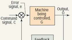
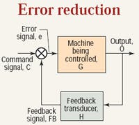
In feedback control, the output of some machine (sometimes called the plant in control system jargon) is measured by a transducer, sent back to a control (this is where the term feedback comes into play), and compared to a command signal (also referred to as the input signal or set point). Comparison consists of the subtraction of the feedback signal from the command, the result of which is the error, or error signal.
The command signal in Figure 1 represents where we want the output to be. The feedback signal is a direct measure of where the output actually is. Therefore, the difference is the error. It is a measure of the amount by which the command and feedback disagree. Mathematically:
e = C – FB
This scheme is also called negative feedback control, because the feedback signal “comes back negatively.” The machine under control, the G block in Figure 1, is said to be error driven because it is, literally, being driven by the error signal. We must take a close look at the error signal because it is misunderstood by many who want to make greater use of feedback control to reap its benefits.
The aim of feedback control is to have a machine into which we can send a command signal and have the output of that machine follow the command. The system in Figure 1 represents a scheme showing the best possibility of achieving that aim.
A common misconception
Electrohydraulic motion control, in its most critical and useful forms, makes ample use of feedback control — notably in the ubiquitous positional servomechanism. However, one of the common interpretations of closed loop control holds that “Because there is feedback control around the machine, and the machine is driven by the error signal, the control system automatically reacts so that the error eventually goes to zero.” This would be very fortuitous, indeed, if only it were true. But it is not.
A century and a half of modern development has sought that end, but, alas, it has never been achieved. In fact, it is safe to say that in any real feedback control system, the error never goes to zero, except, perhaps, for a fleeting moment.
But let’s return to the principles at play by looking at two electrohydraulic systems and comparing them to see how the errors are handled. We’ll then see the implications and the means by which we can cope with them.
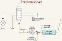
Figure 2. The electrohydraulic positional servomechanism represents the ultimate solution to the motion control problem.
Click to enlarge
The first system is the electrohydraulic positional servomechanism shown in simplified schematic form in Figure 2. Note the line from the cylinder rod to the feedback transducer. It is a solid mechanical linkage and indicates that the feedback transducer is measuring the actual position of the cylinder rod.
The transducer could be a linear variable differential transformer (LVDT), a potentiometer, or the ever-popular magnetostrictive type. The only important point right now is that it produces a signal that is a direct measure of the actual piston rod position. The output (the feedback signal), is a voltage that is proportional to the piston position. For example, the output may be, say, 0 V, with the piston retracted and, say, 10 V when fully extended. The feedback transducer has a gain coefficient that is measured in V/in., V/mm, etc. What it means is that if we know the voltage, we can infer the cylinder’s position. The feedback signal is fed into a comparator — that’s the small circle with the X inside.
Role of the comparator
The comparator performs a mathematical function that subtracts the feedback signal from the position command signal, which is fed into the other input of the comparator. The output of the comparator is the error signal, which goes directly into the amplifier. The function of the amplifier is to boost the error voltage to a higher value and, at the same time, convert the error voltage signal into an error current. The error voltage may be only a few millivolts. However, the servo or proportional valve likely requires volts and amps. The amplifier will provide the boost. Meanwhile, the amplified error signal, labeled current in Figure 2, is fed into the servo or proportional valve.
Here is the system interpretation in its simplified form: Suppose the position command voltage and the feedback voltage are exactly the same value. That requires that the error voltage be zero. If the error voltage is zero, the amplifier output current is zero. If the current into the proportional/ servovalve is zero, its spool will be centered, and the piston rod will not be moving.
On the other hand, if the command voltage is raised, say, by 1 V, and the cylinder has not yet moved, the command and feedback will be unequal, the error will not be zero, and the current to the valve will not be zero. The valve’s spool will shift away from center (null), routing fluid to the cylinder, and the cylinder will move.
This begs the question, “How far will the piston move?” We can answer that in general terms. Assuming the hydraulic plumbing is consistent with the algebraic sign of the current (plus or minus), then the cylinder will move in a direction that increases the output voltage of the feedback transducer. As the cylinder moves, probably extending, the feedback transducer output increases. When it increases by 1 V, the command and feedback voltages will again be equal. The valve current will be zero, the spool centers, and the cylinder stops.
At rest and equal
The key observation in this instance is that the command and feedback are equal when the cylinder stops. Now consider a simple set of values as an example. Suppose a cylinder has a 10.000 in. stroke. Coupled to that is a position transducer that produces 1.000 V of output for each inch of piston travel, with the 0.000-v position coinciding with full retraction. If we put in a command voltage of 3.725 V, what will the cylinder position be when it eventually stops moving? If you answered 3.725 in., you would be correct. However, this has been an idealized and oversimplified explanation.
In a real system, the voltages would not be equal because the cylinder stops due to the force imbalance on the piston — the area of the cap end of the piston is greater than that of the rod end. It is the pressure gain characteristics of the valve that dictate the exact stopping conditions. Pressure gains and their interaction with nonsymmetrical cylinders are beyond the scope of this discussion, and they have to be reckoned with in any precision motion control system.
However, for the sake of brevity, we’ll continue with the oversimplified scenario. So now consider that the system described will produce a feedback signal that is nominally equal to the command when the cylinder stops. Nominally, the error is zero in steady state, a delightful state of affairs. It is a zero error system, and command and feedback are equal in steady state. If they are not equal, the valve shifts and the cylinder moves.
The range required for the command voltage is exactly the same as that for the feedback transducer. But this raises another question: “Are there feedback control systems in which command and feedback signals are not equal in steady-state, even on the so-called nominal basis?” The answer is an emphatic yes!
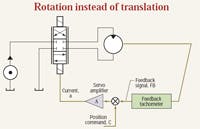
Figure 3. In the motor speed control feedback loop, a continuous rotation motor replaces the cylinder and the feedback transducer is a tachometer.
Click to enlarge
Consider the motor speed control loop of Figure 3. We have a servo or proportional valve, a servo or proportional amplifier, and a constantpressure power unit. This is just as in the case of the positional servomechanism. However, the output actuator is a continuous-rotation motor, and the feedback transducer is a rotational tachometer. This circuit is a speedcontrol loop.
Consider a numerical example. Suppose we had a tachometer with a gain coefficient of 1 V per 1000 rpm. This means that if the motor is turning the tachometer at 3000 rpm, we would expect the tachometer output to be 3.000 V. Now, what is the value of the command voltage needed to operate the motor at 3000 rpm? If you answer 3.000 V, you’re wrong. It will take considerably more than that because there must be a substantial error in this system for the motor to even rotate at any speed. In other words, a command of 3.000 V will produce a speed substantially less than 3000 rpm. Furthermore, we do not have enough information to calculate either the required voltage or the resulting speed! We need to know the gain of the servo amplifier in amperes per volt, the gain of the valve in gpm per ampere, and the speed gain of the motor in rpm per gpm (which is related to the reciprocal of the motor’s displacement).
You must know the gains
It is a tedious task to find these values, and we will return to them, at least in simplified form. Meanwhile, consider the logic behind the statements just presented. Suppose we put in a command of 3.000 V, and then argued that the speed would be 3000 rpm. This would mean that the tachometer output voltage would have to be 3.000 V. This in turn demands that the error voltage be 0 V. But if the error voltage is zero, the amplifier output current must be zero, then the spool must be centered. Therefore, the motor must be turning at 0 rpm!
But we started with the assumption that it was turning at 3000 rpm, and when we follow the loop, we conclude that it must have zero speed! When zero equals 3000, our assumption would be correct. But, alas, zero does not equal 3000, except, perhaps, in the hands of a politician.
What actually happens in the speed control-loop is that with, say, 3.000 V of command signal, the actual speed of the motor will be somewhere between 0 and 3000 rpm, and the control loop will find a point of equilibrium wherein the amount of error voltage produces just enough current to shift the valve just the right amount so as to produce just enough flow to the motor to keep the motor turning at some constant speed. It will not be zero, and it will not be 3000 rpm. It will be some value in between, and the control loop finds that sweet spot with little or no trouble. Our problem at the moment is that we cannot determine what the speed is because we don’t know the gains of the electrohydraulic components.
Back to the command voltage
Now we will look at determining the actual command voltage, but with more complete information. The question will be asked in this way: “If the motor must turn at 3000 rpm, what must the command signal be if the speed gain of the electrohydraulic system is 30,000 rpm/V?”
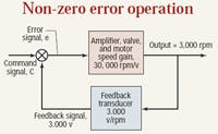
Figure 4. The proportional speed control loop operates with a nominal non-zero error signal.
Click to enlarge
Speed gain is a combined gain that includes the amplifier, the valve, and the motor. It must also include, to some degree, the power unit pressure and the load torque on the motor. It is a very convenient value to have, but it in no way relieves the tedium in finding it from those several constituent machine parts. Experience is simply saying that if we were to know all those parameters, a value of 30,000 rpm/v for the combined speed gain would be reasonable. The problem is set up in Figure 4.
Look at it this way: If we want the motor to turn at 3000 rpm, the amplifier input must be 30,000 times smaller, or 0.100 V. The amplifier input is the error voltage, so the command voltage must be 0.100 V greater than the feedback. And of course, at 3000 rpm, the feedback voltage must be 3.000 V. Therefore, we conclude that it will take 3.100 V of command to produce 3000 rpm of output.
The underlying control system principle that separates the positional servo and the speed control loop is two-fold: First, the electronic control module (the amplifier) is a simple proportional control. It cannot, by itself, reduce the error in the speed loop to zero. Second, we use a position transducer in the position loop and a speed transducer in the speed loop. The position transducer has one integration in the loop, while the speed transducer does not, and it’s the integrator that drives the nominal error to zero in steady state.
There is no integrator in the speed loop, which brings us to another important control system principle: The speed loop will function with a nominal steady-state error of zero if a PID amplifier (PID controller, or, more simply, integral control) is used. Such a move places an artificial integrator in the loop, and voila, a command of 3.000 V will produce 3000 rpm and zero error, nominally speaking, of course.
A bit about integrators
The explanation of integrators within control loops is well beyond what we can get into here. However, to get a feel for what the integrator does, consider a common scenario. Imagine that you must to drive your car at a constant speed, say 65 mph. So you start on straight and level ground, accelerate, and find the equilibrium spot on the accelerator pedal that just maintains your 65 mph. But then you encounter a hill.
The speed goes down, but you see this in your speedometer, and press harder on the accelerator until the speed recovers to 65 mph. At the top of the hill, the opposite occurs, so you back off on the accelerator.
What you have done is mentally perform an integration by always striving to reach 65 mph. If you anticipate the hill and change the accelerator pedal ahead of time, you would be using feed forward. With some skill and practice, and perhaps more of the former than the latter, you can “smooth out the wrinkles” in your car’s speed.
Simple proportional control cannot do this tweaking of the speed as conditions change. Simple proportional control of your car’s speed would be where you find the 65 mph sweet spot when straight and level, and then simply hold a constant accelerator position. The speed will fluctuate up and down as you encounter hills. Integral control can do a better job when properly applied and tuned.
